Coupling external boxes – Sony Multi Interface Shoe Adapter User Manual
Page 1032
Ch
apt
1032
Router Interface Settings (Router Menu)
a) When Matrix Size is 8×1
b) When Matrix Size is 16×1
c) When Matrix Size is 32×1
Coupling external boxes
By coupling a number of external boxes, the number of inputs can be increased.
Here the example of coupling External Box1 and External Box2 is described.
1
In the Router/Tally >Router >External Box Assign menu, select [External
box1] from the
2
In the
3
Turn the knobs to make adjustments.
4
In the
5
In the
6
Turn the knobs to make adjustments.
At this point make the settings of Destination and Level the same as in step
3
.
This automatically couples External Box1 and External Box2, forming an
external box with 40 (8+32) inputs.
Setting the group number of an S-Bus description name
1
In the
[Gp No].
2
Turn the knob to set the following parameter.
a) When setting values 1 to 7 are selected: If the name is not set, the description name for 0
appears. If the description name for 0 is not registered either, the Type and No values
appear.
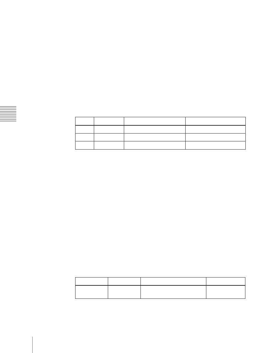
Knob
Parameter
Adjustment
Setting values
1
Source
Source start address
1 to 1017
2
Destination
Destination start address
1 to 1024
3
Level
Level
1 to 8
Knob Parameter
Adjustment
Setting
values
1
Gp No
Group number of S-Bus
description name
0 to 7
a)