Sony Multi Interface Shoe Adapter User Manual
Page 980
Chapt
980
Settings Relating to Function Links (Link Menu)
The status area lists the current setting status of the selected link and the
buses that can be selected.
4
In the
5
Using any of the following methods, select the bus to be the link source,
and press [Bus Set].
• Press directly on the list appearing in the status area.
• Press the arrow keys to scroll the reverse video cursor.
• Turn the knob.
a) Only when [Master Bus] is selected, M/E-1 to M/E-3 Trans PGM, and P/P Trans PGM are
available.
Only when [Linked Bus] is selected, AUX 1 to AUX 48 as Key and MON 1 to MON 8 as
Key are available.
Note
With one of M/E-1 to M/E-3 Trans PGM and P/P Trans PGM selected
for [Master Bus], the link setting become effective as soon as you start
moving the fader lever.
6
In the
7
Referring to step
5
, select the bus to be the link destination, and press [Bus
Set].
8
Turn the knob to select the link table, and press [Link Table Set].
For more information about link tables, see the following item.
The selected link table number is confirmed, and this is reflected in the
status area.
To delete a link
Select the link you want to delete, then press [Clear] in the Switcher >Link
>Internal Bus Link menu.
Knob
Parameter
Adjustment
Setting values
2
No
Bus selection
1 to 190
a)
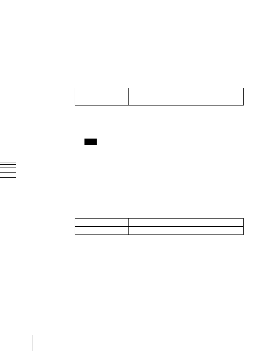
Knob
Parameter
Adjustment
Setting values
3
Link Table No
Link table selection
1 to 8