Setting a link table – Sony Multi Interface Shoe Adapter User Manual
Page 885
885
Overall Control Panel Settings (Config Menu)
Chap
1
In the Panel >Config >Link/Program Button >External Bus Link menu,
press [Link Matrix Adjust].
The Link Matrix Adjust menu appears.
The status area shows the status of the currently selected matrix, and a list
of the source and destination start addresses that can be selected.
In this menu too, you can use the knobs to select the link for the setting.
2
Using any of the following methods, define the position of the matrix to be
linked.
• Press directly on the list in the status area.
• Press the arrow keys to scroll the reverse video cursor.
• Turn the knobs.
3
To confirm a source address selected in step
2
, press [Source Set], to
confirm a destination address press [Destination Set], and to confirm a
level press [Level Set].
This confirms the selection, which is reflected in the status area.
Setting a link table
For the link selected in the External Bus Link menu, make the settings as
follows.
1
In the Panel >Config >Link/Program Button >External Bus Link >Link
Matrix Adjust menu, press [Link Table Adjust].
The Link Table Adjust menu appears.
The status area lists the status of the currently selected link, combinations
of video signals and sources, and the sources that can be selected.
2
Using any of the following methods, select the switcher cross-point button
and the matrix source to be linked to the button.
• Press directly on the list in the status area.
• Press the arrow keys to scroll the reverse video cursor.
• Turn the knobs.
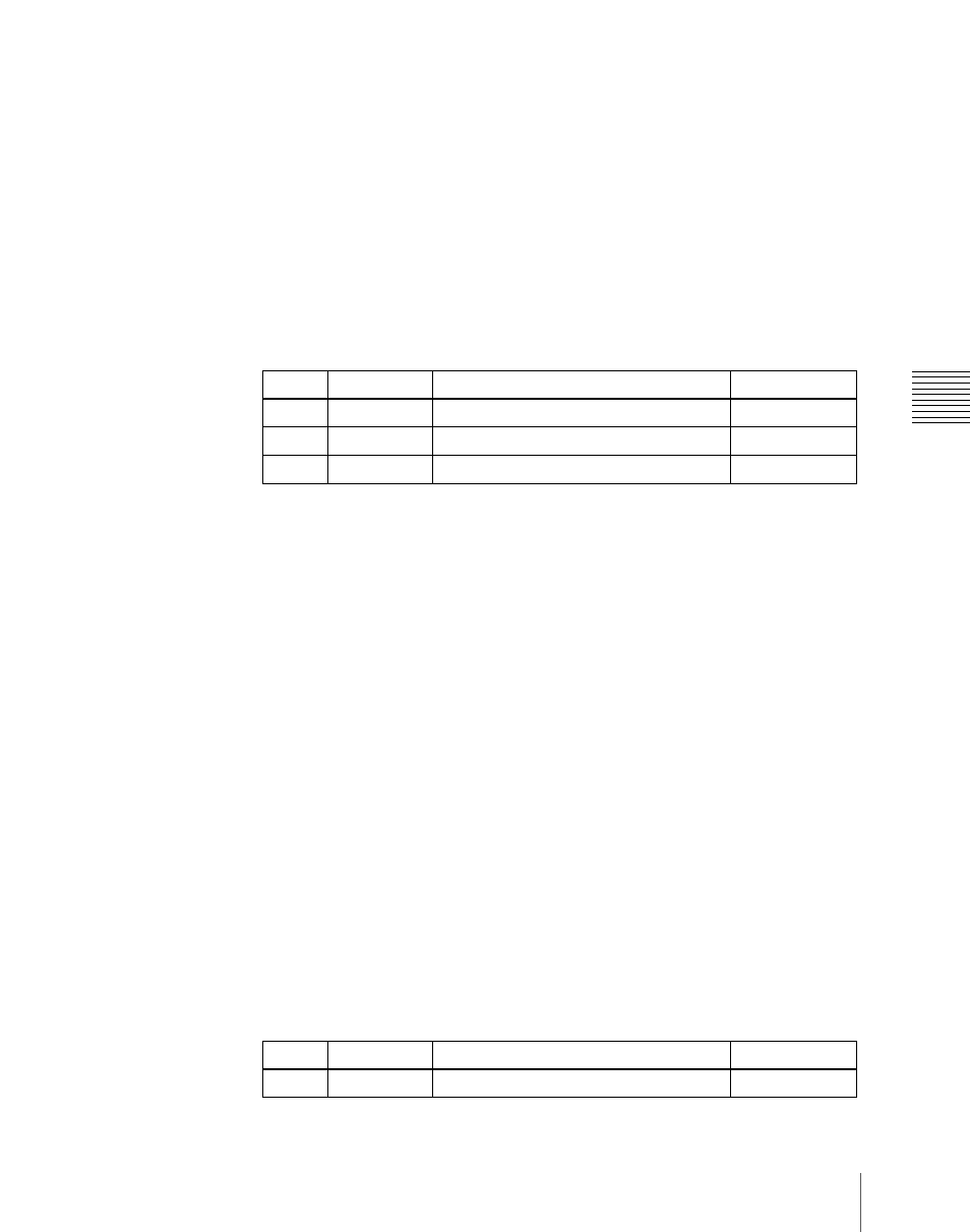
Knob
Parameter
Adjustment
Setting values
2
Source
Source start address
1 to 897
3
Destination
Destination start address
1 to 897
4
Level
Level
1 to 8
Knob
Parameter
Adjustment
Setting values
1
Main No
Switcher cross-point button
1 to 128