Sony Multi Interface Shoe Adapter User Manual
Page 139
139
Executing a Transition
Cha
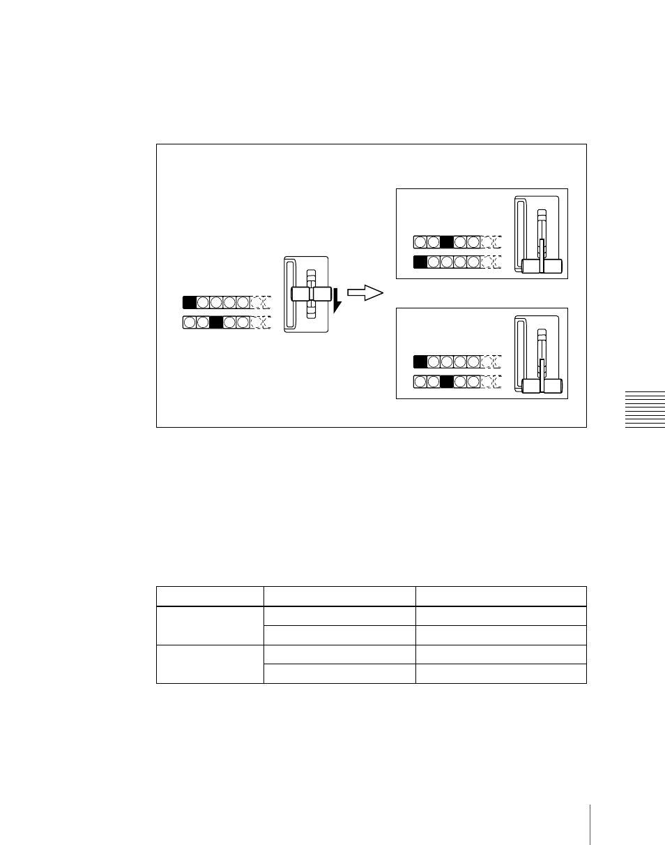
background output is always from the background A bus. This is called “flip-
flop mode.”
The alternative is known as “bus fixed mode,” in which there is no bus
interchange. In this mode, when the fader lever is at the top of its travel the
output from the A bus is always 100%, and when the fader lever is at the bottom
of its travel the output from the B bus is 100%.
Flip-flop mode and bus fixed mode
In the bus fixed mode there is a fixed relationship between the position of the
fader lever and the signal output on each bus. Depending on the direction of the
transition, the fader lever must therefore always be moved in a particular
direction, as shown in the following table. This does not affect an auto
transition, which is executed regardless of the fader lever direction.
Fader lever operating direction in bus fixed mode
• When a transition applies to a combination of more than one of the
background and keys 1, 2, 3, and 4, then the transition for all of these must
be in the same direction complying with the above table.
A
B
BLACK
BLACK
A
B
BLACK
BLACK
A
B
BLACK
BLACK
Buttons lit
Fader
lever
Flip-flop mode
Bus fixed mode
Next transition
Transition direction
Fader lever movement
Background
A
t
B
Downward
B
t
A
Upward
Keys 1, 2, 3, and 4
On
t
Off (deletion)
Downward
Off
t
On (insertion)
Upward