Making switcher processor gpi input settings – Sony Multi Interface Shoe Adapter User Manual
Page 987
987
Interfacing With External Devices (Device Interface Menu)
Cha
Note
When REMOTE1 and REMOTE2 are respectively assigned to DME1 and
DME2, you can switch the AUX bus from the DME (DME-3000/7000)
connected to these ports.
At this time, connect the DME input video signals and key signals as follows.
• DME1 video input: AUX1 output
• DME1 key input: AUX2 output
• DME2 video input: AUX4 output
• DME2 key input: AUX5 output
Note that for a DME external video signal, you can select any of AUX1 to
AUX14 on the DME. Connect to the selected AUX bus.
Making Switcher Processor GPI Input Settings
The same GPI input is used for switcher processor control and for DME
control.
1
In the Switcher >Device Interface menu, press [GPI Input].
The GPI Input menu appears.
2
Using any of the following methods, select the settings.
• Press directly on the list in the status area.
• Press the arrow keys to scroll the reverse video cursor.
• Turn the knobs.
3
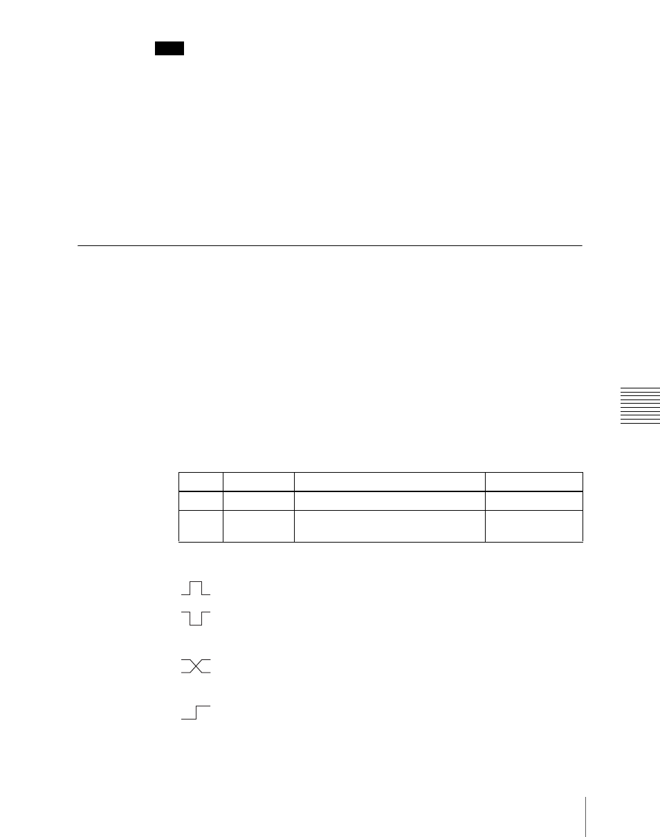
In the
(Rising Edge):
Apply the trigger on a rising edge of an input pulse.
(Falling Edge):
Apply the trigger on a falling edge of an input
pulse.
(Any Edge):
Apply the trigger on a change in the polarity of the
input signal.
(Level):
Carry out the specified operation when the input is low or
high.
No Operation:
Apply no trigger on an input pulse.
Knob
Parameter
Adjustment
Setting values
1
Port
Port selection
1 to 8
2
No
Selection of number for action to be
assigned
1 to 8