1 pin connections – HEIDENHAIN TNC 407 (243 020) Technical Manual User Manual
Page 95
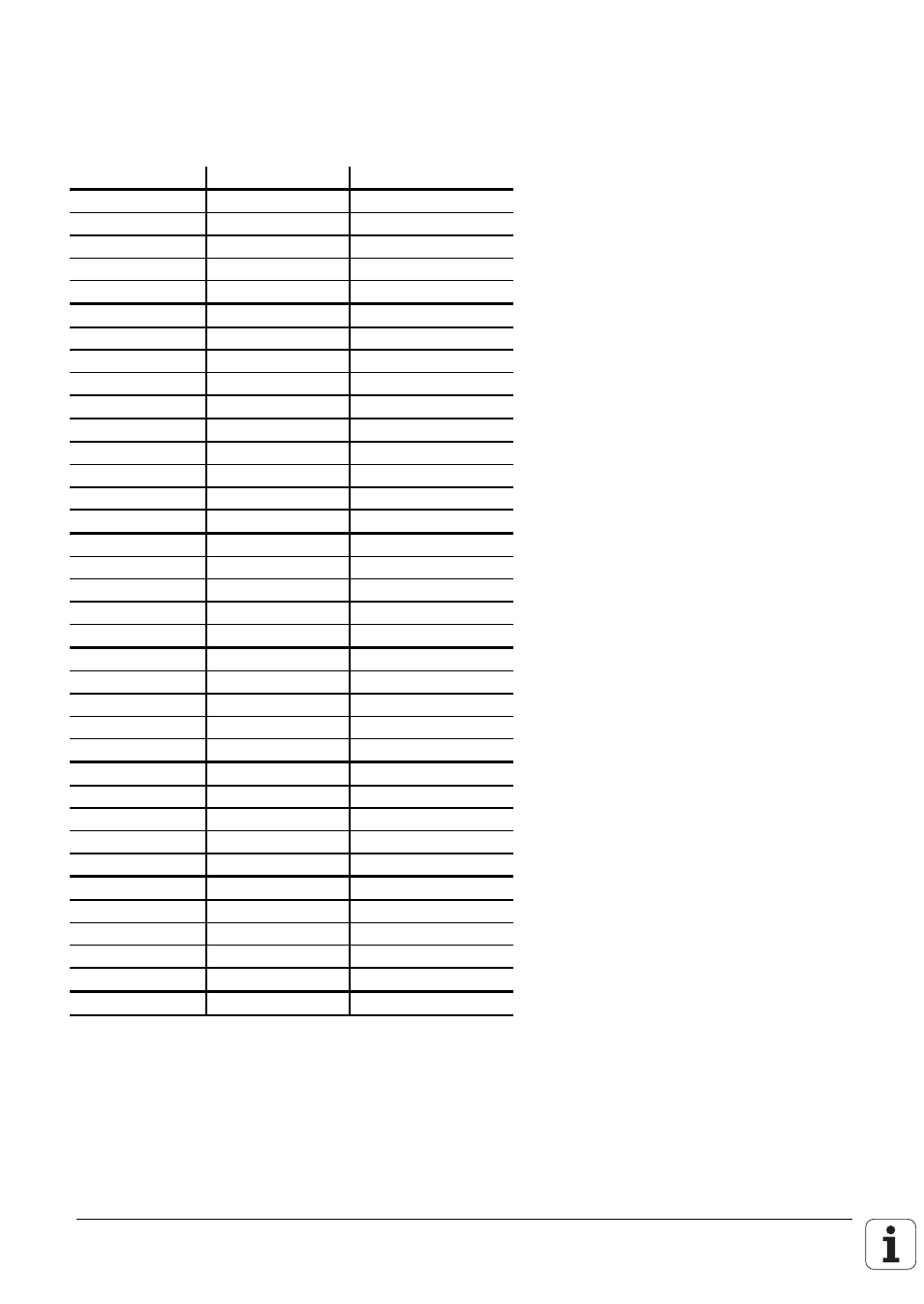
12.1 Pin connections
X46 Machine operating panel
Flange socket with female connector insert (37-pin)
Pin number
Assignment
Key on MB 410
1
I128
X–
2
I129
Y–
3
I130
Z–
4
I131
IV–
5
I132
V–
6
I133
X+
7
I134
Y+
8
I135
Z+
9
I136
IV+
10
I137
V+
11
I138
FN1
12
I139
FN2
13
I140
FN3
14
I141
FN4
15
I142
FN5
16
I143
Spindle on
17
I144
Spindle off
18
I145
Coolant on/off
19
I146
NC start
20
I147
NC stop
21
I148
Rapid traverse
22
I149
Black
23
I150
Black
24
I151
25
I152
26
O0
27
O1
28
O2
29
O3
30
O4
31
O5
32
O6
33
O7
34, 35
0 V (PLC)
1)
36, 37
+ 24 V (PLC)
2)
Housing
External shield
The PLC inputs I128 to I152 must be supplied with power only from pins 36 and 37, since this
power supply is properly safeguarded.
1)
Externally available PLC reference potential for the outputs O0-O7
2)
Externally available (via fuse) PLC supply voltage for the inputs.
This manual is related to the following products: