HEIDENHAIN TNC 407 (243 020) Technical Manual User Manual
Page 60
1.
2.
3
.12"
G
7
8
9
F
A
B C D
22
.87"
5
.20"
E
3
.12"
4
6
5
H
K
10
4
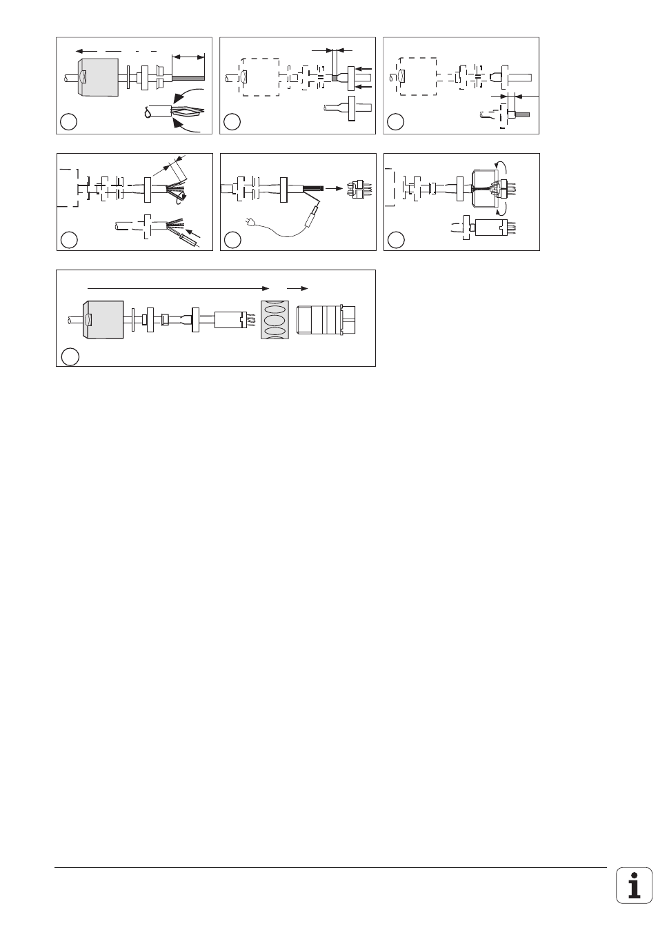
Push parts A – D on to the cable, alternatively assemble the screw connection for the
armouring according to diagram 3. Strip back 22 mm of the outside sleeving. Unpick the
outer screen and fold back.
5
Cut off the outer screen to a length of 3 mm and slide the screen contact sleeve E
between the internal sleeving and the braided screen.
6
Cut back the internal sleeving to a length of 5 mm.
7
1. twist the inner screen together.
2. insulate the twisted inner screen with heat-shrinkable sleeving.
8
Strip off the insulation on all leads for 3 mm, tin and solder in accordance with the
connection diagram to G or G1.
9
Assemble part F.
10
Push the connector together.
The following points must be observed when assembling the measuring system:
.The inner screen (pin 9) must not make any electrical connection with the outer screen (connector
housing).
.The outer screen of the measuring system cable must have an electrical connection with the
connector housing.
.The measuring system is grounded through its mechanical fixings, the mounting block in the case
of encapsulated systems, and the housing of the scale.
.When using external pulse-forming electronics (EXE) the ground must be electrically connected
with the frame of the machine. Necessary cable cross-section
≥
∅
6 mm².
.Encapsulated linear measurement systems should be connected to compressed air.