2 flow-diagram, 1 tnc 415 – HEIDENHAIN TNC 407 (243 020) Technical Manual User Manual
Page 247
5.2 Flow-diagram
The external electronics must meet the specified conditions. In particular, the acknowledgement for
"Control ready" must reach the TNC 415 after a maximum of 114 ms (for the TNC 407: 146 ms) .
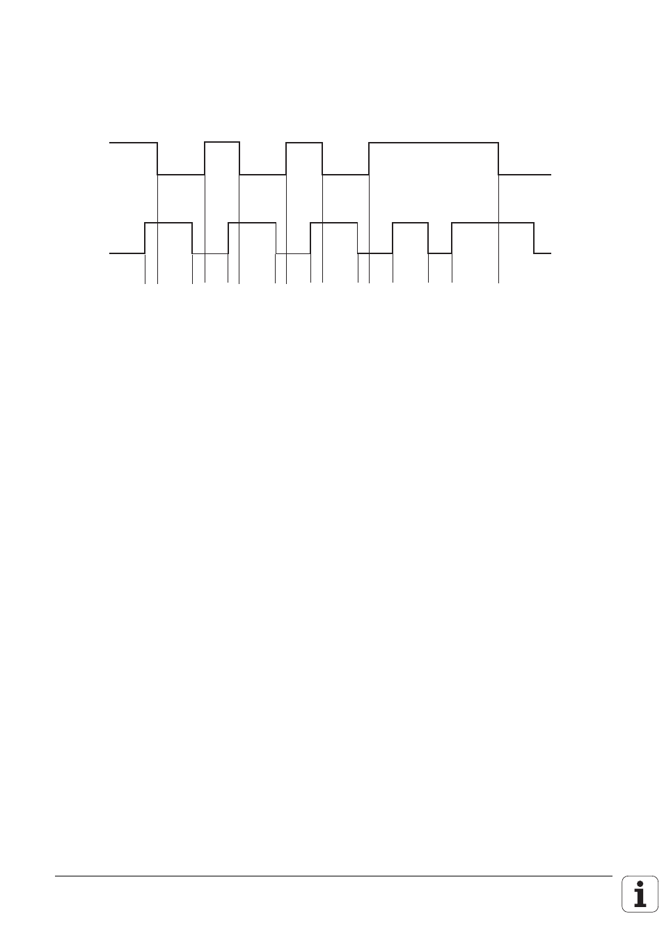
5.2.1 TNC 415
X41/34
X42/4
1 2 3 4 5 6 7 8 9 10 11 12 13 14 15 16 17
VDU display
1.
Wait for control voltage.
RELAY EXT. DC VOLTAGE
MISSING
2.
Recognize the control voltage on X42/4 and switch-off
of the control-is-ready signal on X41/34
by the first microprocessor (t < 66 ms).
3.
Maximum time during which the acknowledgement of
Control readiness on X42/4 must go to 0 (t < 114 ms).
If exceeded
EMERGENCY STOP DEFECTIVE
4.
Recognize the acknowledgement and set X41/34
(t < 20 ms).
5.
Wait for control voltage.
RELAY EXT. DC VOLTAGE
MISSING
6.
Recognize the control voltage on X42/4 and switch-off
of the control-is-ready signal on X41/34
by the second microprocessor (t < 66 ms).
7.
Maximum time during which the acknowledgement of
control readiness on X42/4 must go to 0. (t < 114 ms).
If exceeded
EMERGENCY STOP DEFECTIVE
8.
Recognize the acknowledgement and set X41/34
(t < 20 ms).
9.
Wait for control voltage.
RELAY EXT. DC VOLTAGE
MISSING
10. Recognize the control voltage on X42/4 and switch-off
of the control-is-ready signal on X41/34
by the third microprocessor (t < 66 ms).