9 touch probe, 1 standard touch probe cycles – HEIDENHAIN TNC 407 (243 020) Technical Manual User Manual
Page 301
4-176
TNC 407/TNC 415/TNC 425
9 Touch probe
01.98
9 Touch probe
The following 3D touch probes can be connected:
The triggering touch probes
- TS
120 with cable transmission and integrated interface electronics,
- TS
511 with infrared transmission of the switch signal and connected by a separate interface
electronics unit (APE)
- TT
110 for tool calibration
- The TNC 415/425 also supports the TM
110 measuring touch probe.
The chapter "Mounting and Electrical Installation" contains instructions for connecting the touch
probes. Machine parameters MP6010, MP6200 and MP6500 determine which touch probes are
connected. The machine tool builder must ensure that the spindle locks as soon as the touch probe
has been inserted.
9.1 Standard touch probe cycles
The touch probe can be controlled either with the probing cycles in the "Manual" and "Electronic
Handwheel" modes or by the "Touch Probe" function in the NC program (see User's Manual). The
touch probe is interfaced to the measuring conditions using machine parameters.
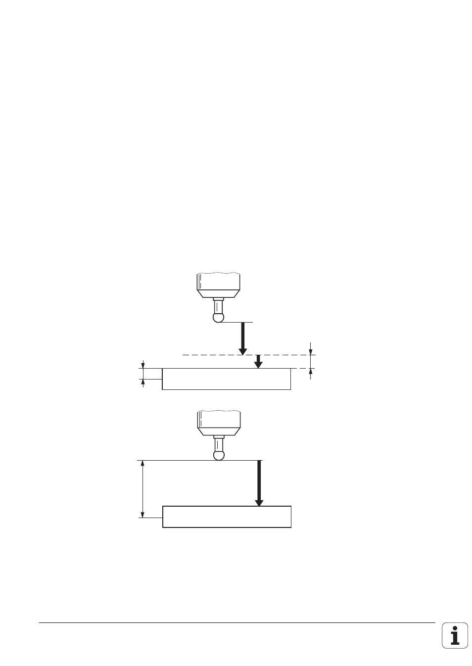
Touch probe function
"Reference Plane"
Max. measuring range
(MP6130)
Touch probe cycles
in the "Manual" and
"Electronic
Handwheel"
operating modes
Max. measuring range
(MP6130)
F
1
F
2
F
2
Setup clearance
(MP6140)
F1 = Rapid traverse during probing cycle:
MP6150 for triggering touch probe MP6200 = 0
MP6361 for measuring touch probe MP6200 = 1
F2 = Probing feed rate:
MP6120 for triggering touch probe MP6200 = 0
MP6360 for measuring touch probe MP6200 = 1