HEIDENHAIN TNC 407 (243 020) Technical Manual User Manual
Page 712
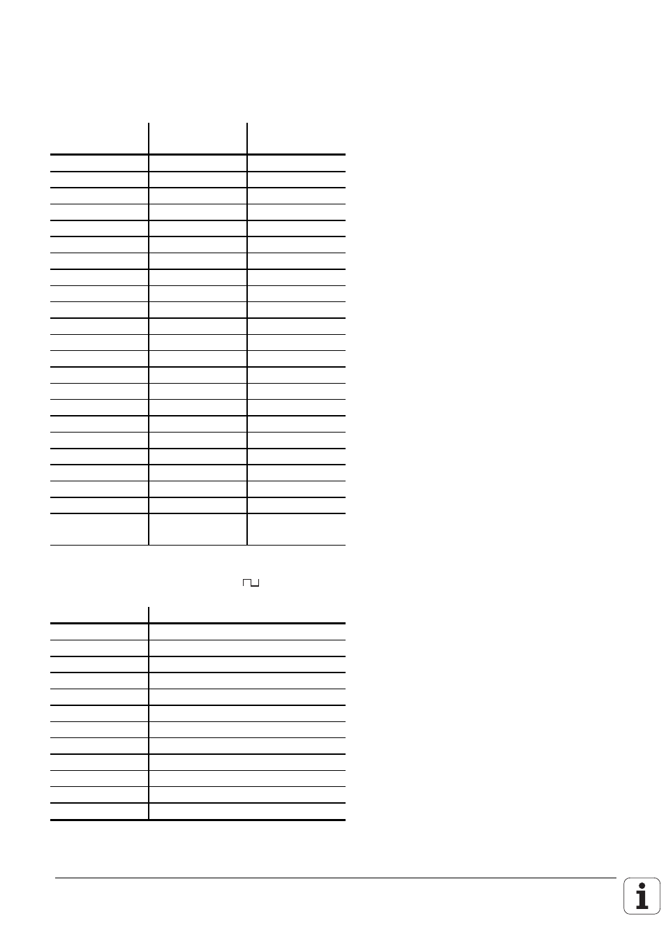
Pin layout
X25 data interface RS-422/V.11 and RS-232-C/V.24
Flange socket with female insert (25-pin)
Pin No.
Assignment
RS-422/V.11
Assignment
RS-232-C/V.24
1
Screen
2
RxD
3
TxD
4
CTS
5
RTS
6
DTR
7
GND Signal
8
spare
9
RxD
___
10
CTS
___
11
TxD
___
12
RTS
___
13
DSR
___
14
DTR
___
15
DTR
16, 17, 18
spare
19
GND Signal
20
DSR
DSR
21
RxD
22
CTS
23
TxD
24
RTS
25 Chassis
Outer screen
GND Chassis
X5 Measuring system Input 5 (
)
Pin No.
Assignment
5
U
a1
6
U
a1
––—–
8
U
a2
1
U
a2
––—–
3
U
a0
4
U
a0
––—–
7
U
aS
––—–
2
+ 5 V (U
P
)
12
+ 5 V (U
P
)
11
0 V (U
N
)
10
0 V (U
N
)
9 (spring)
Screen = Chassis
This manual is related to the following products: