3 plc program example – HEIDENHAIN TNC 407 (243 020) Technical Manual User Manual
Page 371
15.3 PLC program example
This section describes a tool changer and contains the basic sequence diagrams of the
corresponding PLC programs. When creating a program the constraints on the PLC program
sequence must be remembered (set buffer markers etc.).
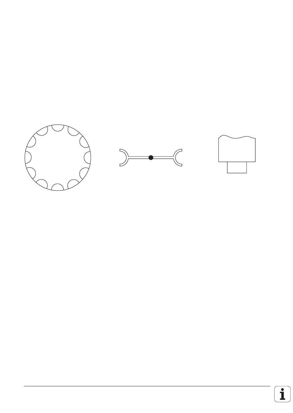
The example describes a tool changer with the following features:
- Up to 254 tools
- Variable pocket coding (MP7480 = 4)
- Special tools are permitted
- Next tool standby with TOOL DEF
- Toolchange with TOOL CALL
- Tools with no pocket number defined in the tool table can be changed by hand
- Double changing arm
- Special tools variable (M2601 = 0)
SPIREG
GRE1
GRE2
ISTREG
The following sequence diagram uses variables for greater clarity. In the PLC program these
variables are replaced by byte addresses.
ISTREG
=
B10
=
Pocket number at the tool-change position of the tool magazine
GRE1
=
B11
=
Pocket number of tool in changing arm facing tool magazine
GRE2
=
B12
=
Pocket number of tool in changing arm facing spindle
SPIREG
=
B13
=
Pocket number of tool in spindle