1 connection diagram – HEIDENHAIN TNC 407 (243 020) Technical Manual User Manual
Page 246
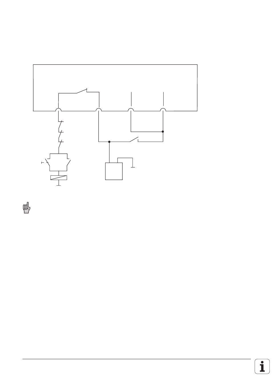
5.1 Connection diagram
Under fault conditions the control-is-ready output should switch off the 24-volt supply. Because of
the enormous importance of this function this output is tested by the control every time the mains
power is switched on.
Basic circuit diagram:
+ -
Logic unit
Switch opens briefly when the control voltage
of each microprocessor is switched on
X41/34 X44/2 X44/1 X42/4
"Control is
ready"
24V not
interruptible
24V
interruptible
"Control ready"
feedback
EMERGENCY
STOP
buttons
Control
voltage
on
k1
k1
K1
24 V
PLC
This is merely a suggestion for switching. The machine manufacturer must ensure that all
necessary safety specifications are met.
This manual is related to the following products: