3 plc inputs/outputs on the pl 400 – HEIDENHAIN TNC 407 (243 020) Technical Manual User Manual
Page 87
11.3.3 PLC inputs/outputs on the PL 400
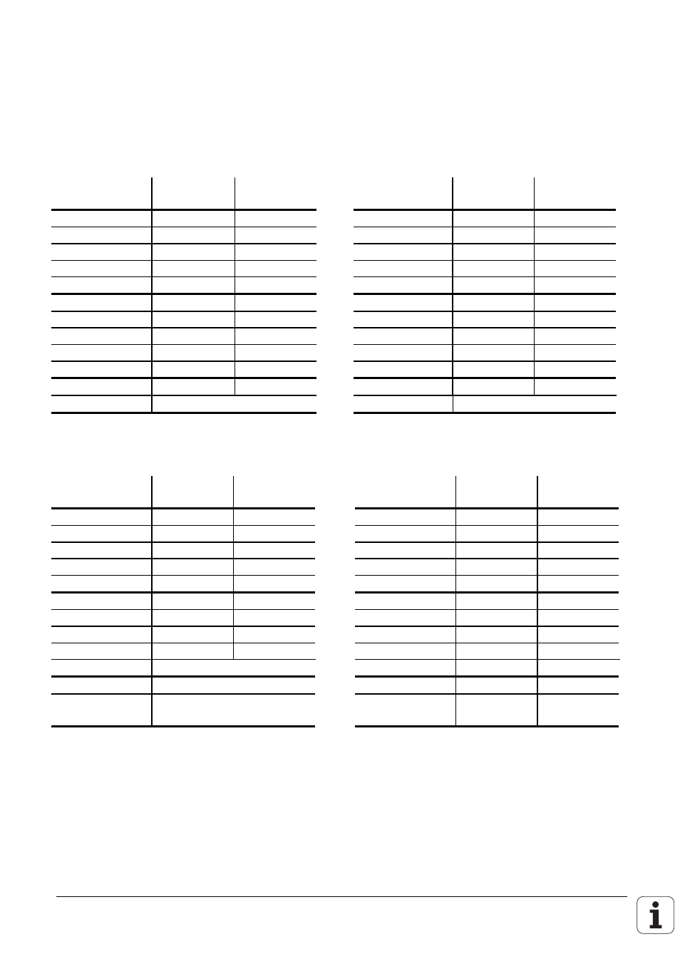
The PLC inputs/outputs on the PL 400 are spread over nine connectors assigned as follows:
Cables with a core cross-section
≥
dia. 0.14 mm² Cu must be used to connect the PLC inputs and
outputs. Maximum cable length 20 m.
X1
X2
Pin number
Assignment
Assignment
Pin number
Assignment
Assignment
PL 400 #1
PL 400 #2
PL 400 #1
PL 400 #2
1
O32
O64
1
O43
O75
2
O33
O65
2
O44
O76
3
O34
O66
3
O45
O77
4
O35
O67
4
O46
O78
5
O36
O68
5
O47
O79
6
O37
O69
6
O48
O80
7
O38
O70
7
O49
O81
8
O39
O71
8
O50
O82
9
O40
O72
9
O51
O83
10
O41
O73
10
O52
O84
11
O42
O74
11
O53
O85
12
Do not use
12
Do not use
X3
X4
Pin number
Assignment
Assignment
Pin number
Assignment
Assignment
PL 400 #1
PL 400 #2
PL 400 #1
PL 400 #2
1
O54
O86
1
I126
I254
2
O55
O87
2
I74
I202
3
O56
2)
O88
2)
3
I73
I201
4
O57
2)
O89
2)
4
I72
I200
5
O58
2)
O90
2)
5
I71
I199
6
O59
2)
O91
2)
6
I70
I198
7
O60
2)
O92
2)
7
I69
I197
8
O61
2)
O93
2)
8
I68
I196
9
O62
2)
O94
2)
9
I67
I195
10
Control ready
10
I66
I194
11
Do not use
11
I65
I193
12
+24 V not interruptible by
ext. EMERGENCY STOP
1)
12
I64
I192
1)
+24V must always be connected even if the non-interruptible outputs are not used.
2)
Outputs not interruptible by ext. EMERGENCY STOP