Hardware, 2 hardware – HEIDENHAIN TNC 407 (243 020) Technical Manual User Manual
Page 711
10-3
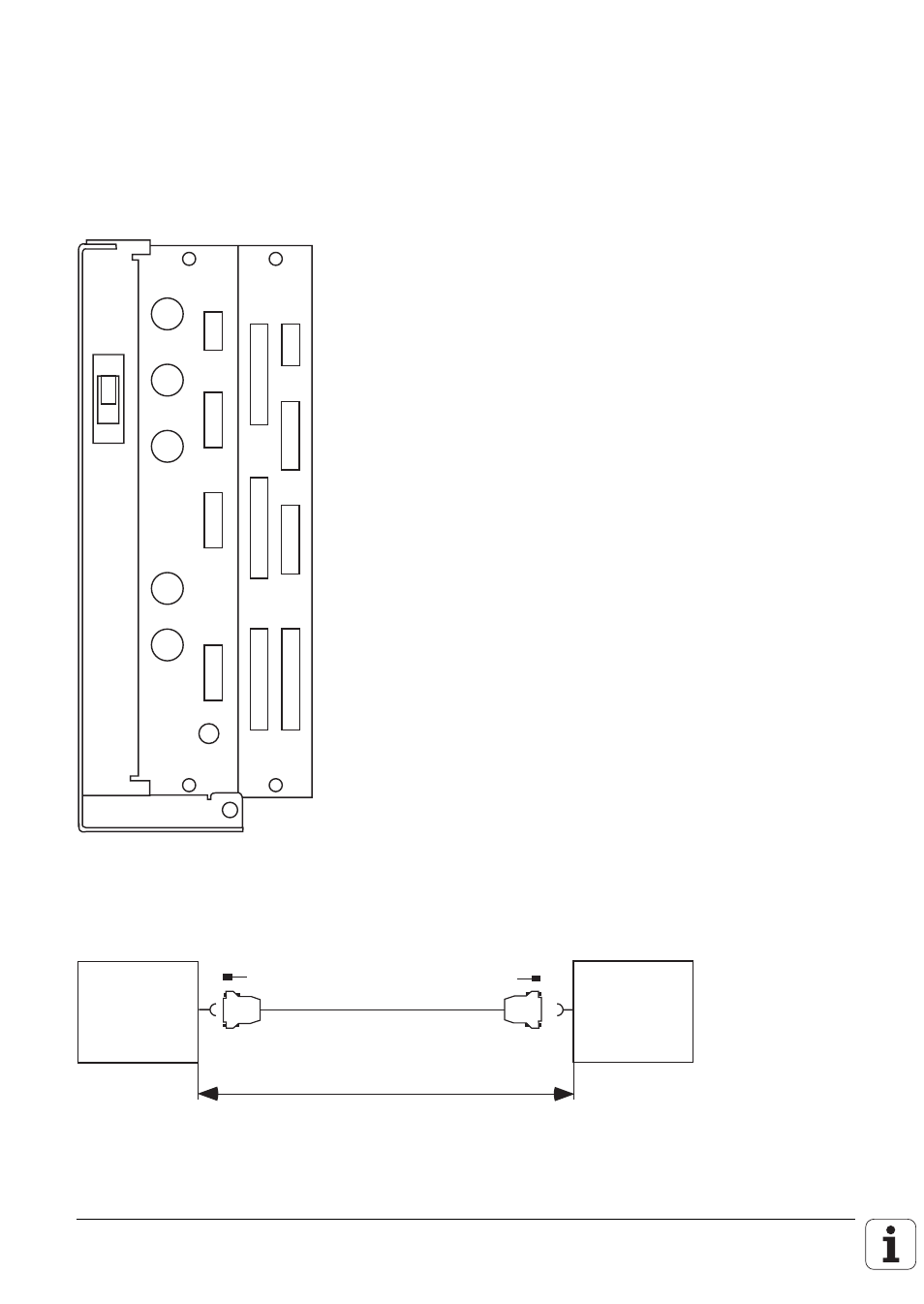
1.2 Hardware
Differences in hardware between LE 234.003 and LE 360 C:
- the X25 connector contains the RS-232-C/V.24 and the RS-422/V.11
- there is no X4 measuring system input (sinus)
- X5 measuring system input (square) is additional
X1
X2
X3
X5
X6
X11
X12
X8
B
X24
24V
X31
X9
X21
X22
X23 X27
X26
X25
Control loop board
X1 = Measuring system 1 (~)
X2 = Measuring system 2 (~)
X3 = Measuring system 3 (~)
X5 = Measuring system 5 ( )
X6 = Measuring system S ( )
X8 = Nominal value output 1,2,3,4,S
X9 = Screen unit (for commissioning only)
B = Operational ground
X21 = PLC output
X22 = PLC input
X23 = TNC keyboard (TE)
(for commissioning only)
X24 = 24 V supply for PLC
X25 = RS-422/V.11 data interface (V.24/RS-232)
X31 = 24 V supply for LE
X11, X12 and X26 are not required.
X4 is not fitted.
Connecting cable
LE 234.003
max. 50 m
LE 407/415
Id.-Nr. 265 479 ..
292 123 ..