2 ts 511 – HEIDENHAIN TNC 407 (243 020) Technical Manual User Manual
Page 68
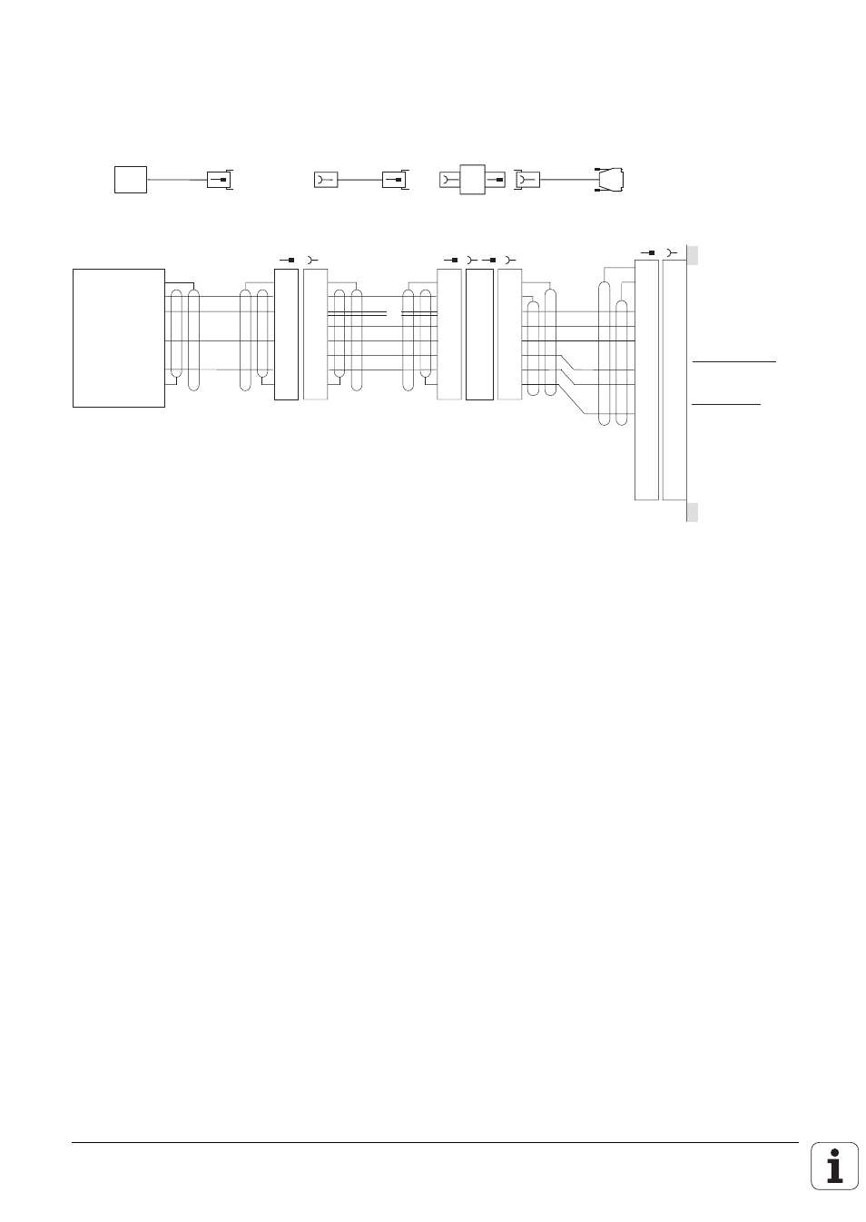
8.2.2 TS 511
The TS 511 touch probe system can only function together with a transmitter/receiver unit (SE 510)
and interface electronics (APE 510).
Touch probe input
Internal screen (0V)
Standby
Start
15V
±
10% (U
P
)
Battery warning
0V (U
N
)
Trigger signal
X12
Id.-Nr. 274 539 ..
max. 7 m
max. 30 m
Id.-Nr. 274 540 ..
SE 510
3 m
1
2
3
4
5
6
7
8
9
10
11
12
13
14
15
1
2
3
4
5
6
7
8
9
10
11
12
13
14
15
•
•
•
APE
510
7
5
3
2
6
1
4
GY
YL
BN
BL
WH
GN
1
2
3
4
5
6
7
•
1
2
3
4
5
6
7
1
2
3
4
5
6
7
•
•
GY
YL
BN
WH
GN
BL
WH
BN
GY
GN
WH/
BK
0V
U
P
Flash signal
IR-signal
Internal
screen (0V)
SE 510
WH/BN
APE 510
WH/
BK
RD
The signals may be inverted by changing the switch positions S1 to S4 in the APE 510.
See operating instructions TS 511.
Please install the transmitter/receiver unit SE 510 either insulated from, or electrically connected to
the machine, as it must take up a definite potential, also under vibration. The earthing screw of
the APE 510 must be joined to the machine signal ground by a potential compensating lead
(
≥
∅