Reference pulse inhibit input, Connector assignment, Connecting cable – HEIDENHAIN TNC 407 (243 020) Technical Manual User Manual
Page 65: 7 reference pulse inhibit input, 1 connector assignment x10, 2 connecting cable
01.98
TNC 407/TNC 415/TNC 425
7 Reference pulse inhibit input
3-35
7 Reference pulse inhibit input
The reference pulse inhibit input can be used to suppress the evaluation of the reference pulse input
of each of the six measuring systems. This is achieved by simply applying a positive potential (13 V
to +30.3 V) to the appropriate reference pulse inhibit input. Pin 9 of the female connector X10
(reference pulse inhibit) must be connected to 0 V of the PLC-power supply.
The reference pulse inhibit inputs are only available in the LE 415 A. These inputs are
normally unused. See also Chapter "Machine Integration".
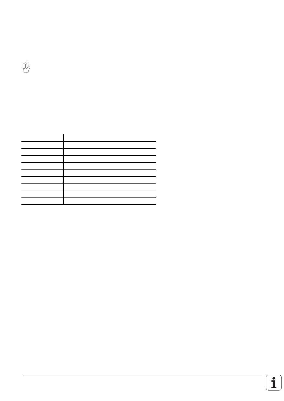
7.1 Connector assignment
X10
X10 Reference pulse inhibit (LE 415 A only)
Flange socket with female connector insert (9-pin)
Pin number
Assignment
1
Screen
2
Reference pulse inhibit input X1
3
Reference pulse inhibit input X2
4
Reference pulse inhibit input X3
5
Reference pulse inhibit input X4
6
Reference pulse inhibit input X5
7
Reference pulse inhibit input X6
8
Do not use
9
0 V (PLC)
7.2 Connecting cable
Standard commercially available screened cables can be used for the connections to the reference
pulse inhibit inputs.
HEIDENHAIN can deliver a 9-pin D-subminiature connector (Id.-Nr. 244 503 ZY) for this purpose.