HEIDENHAIN TNC 407 (243 020) Technical Manual User Manual
Page 318
The probing feed rate is calculated from the calculated rotational speed and the measuring tolerance
given in MP6510.
v= Meas. tolerance
n
×
Meas. tolerance =
Meas. tolerance [mm] depending on MP6507
n =
Rotational speed [rpm]
MP6507 defines the method of calculating the probing feed rate:
MP6507=0: Calculation of the feed rate with constant tolerance
This setting guarantees that the measuring tolerance remains constant regardless of the tool radius
(MP6510). If the tool is very large, however, the necessary probing feed rate comes so close to zero
that it falls below the lowest programmable increment. The smaller the maximum surface cutting
speed and the permissible measuring error, the sooner this effect becomes noticeable.
MP6507=1: Calculation of the feed rate with variable tolerance
In this setting the permissible measuring tolerance changes depending on the tool radius. This
ensures that there is a probing feed rate even for large tool radii. The measuring tolerance changes
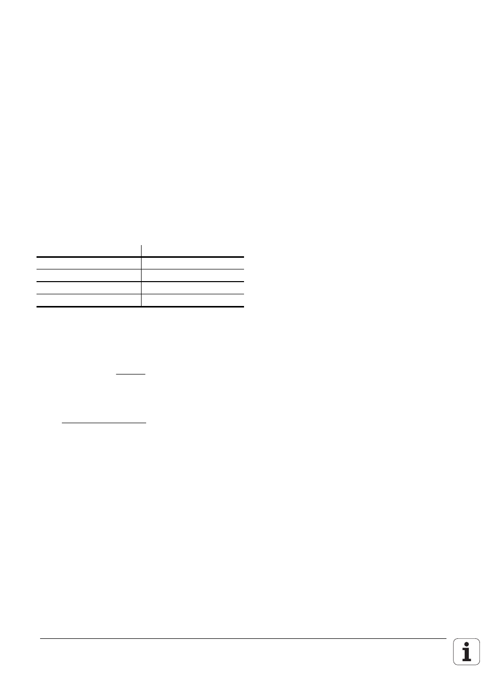
according to the following table:
Tool radius
Measuring tolerance
up to 30 mm
MP6510
30 to 60 mm
2
×
MP6510
60 to 90 mm
3
×
MP6510
90 to 120 mm
4
×
MP6510
etc.
MP6507=2: Constant probing feed rate
The probing feed rate remains constant regardless of the tool. The absolute measuring error grows
linearly with increasing tool radius.
Meas. tolerance =
r
5 [mm]
×
MP6510
r =
Tool radius [mm]
MP6510 =
Max. permissible measuring error [mm]
v = Meas. tolerance
×
n
v =
MP6570
MP6510
10
×
× ×
−
π
10
3
v =
Probing feed rate [m/min]
MP6570 = Maximum permissible surface speed at the
cutting edge [m/min]
Markers in the PLC
Marker M2390 is set when a tool measuring cycle is started. Marker M2391 indicates whether a
cycle for tool measurement or tool inspection was activated. If inspection shows that one of the
entered tolerances is exceeded, the tool is inhibited and Marker M2392 or M2393 is set.
Markers M2502, M2503, M2022, M2023, M2025 and M2026 function as in the standard probing
cycles. The cycles for tool measurement must therefore also be released by the PLC with Marker
M2503.
If the spindle is oriented directly by the NC (MP6560 = –1), Marker M2499 must be reset by the
PLC.