HEIDENHAIN TNC 407 (243 020) Technical Manual User Manual
Page 59
3-29
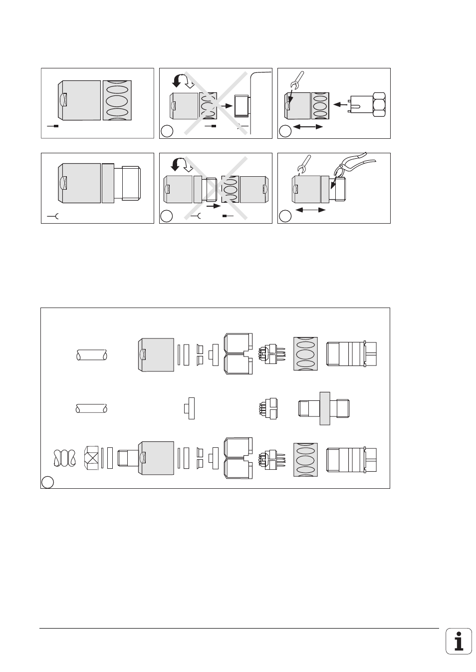
Assembly of the connector 237 524 ..
Assembly of the coupling 237 525 ..
1a
1b
2.
1.
3.
2a
2b
1.
3.
2.
1a + 2a Do not open connector or coupling with a mating connector!
1b
The special assembly tool Id.-Nr. 236 148 01 and a 22 mm spanner are absolutely
necessary to assemble the connector.
2b
An adjustable pipe-wrench with plastic jaws is required to assemble the coupling.
A
B C D
E
F
G
H
K
C1
G1
H1
Z Y X
A1
3
3
The diagram shows the various component parts of the connector and the coupling, and
the two different versions of the screw connections for the armoured version PG7 and
PG9. The screw connection PG9 with the Id.-Nr. 209 629 01, consisting of the parts X
1
, Y
1
,
Z
1
, must be ordered separately.
This manual is related to the following products: