Touch probe system input, Connector assignment x12, 8 touch probe system input – HEIDENHAIN TNC 407 (243 020) Technical Manual User Manual
Page 66: 1 connector assignment x12
3-36
TNC 407/TNC 415/TNC 425
8 Touch probe system input
01.98
8 Touch probe system input
The following 3D touch probe systems are available from HEIDENHAIN:
–
TS 120 with cable transmission and integrated APE (interface electronics)
–
TS 511 with infrared transmission of the trigger signal and connectable via APE (interface
electronics)
–
TT 110 for workpiece measurement
–
The TNC 415 and TNC 425 can also support the measuring touch probe system TM 110
For start-up and adjustment of the 3D-touch probe systems see Chapter "Machine Integration".
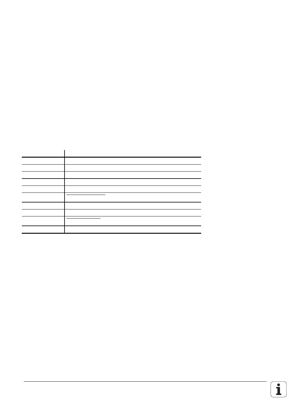
8.1 Connector assignment
X12
X12 Touch probe system
D-subminiature female connector (15-pin)
Pin number
Signal designation
1
Inner screen (0 V)
3
Ready/standby
4
Start
5
+15 V ± 10 % (U
P
)
6
+ 5 V ± 5 % (U
P
)
7
Battery warning
8
0 V (U
N
)
9
Trigger signal
10
Trigger signal²
2, 11 to 15
Do not use
2 Stylus in rest position = signal high