HEIDENHAIN TNC 407 (243 020) Technical Manual User Manual
Page 384
16 Commissioning and start-up procedure
4-259
–
Tuning of the drive amplifier:
As far as the control is concerned, the actual servo-loop consists of the drive amplifier, motor
and axis slide (see section "Servo positioning"). The servo-loop must be tuned before the position
control loop in the control can be optimized.
To achieve this, a battery supply is used to apply a (9 V) step function to the nominal value input
of the drive amplifier. The step response can be recorded by an oscilloscope via the tachometer
signal. The axis should be loaded with the permissible workpiece weight during the acquisition of
the step response. The subordinate control loop (current control, spindle speed control) must be
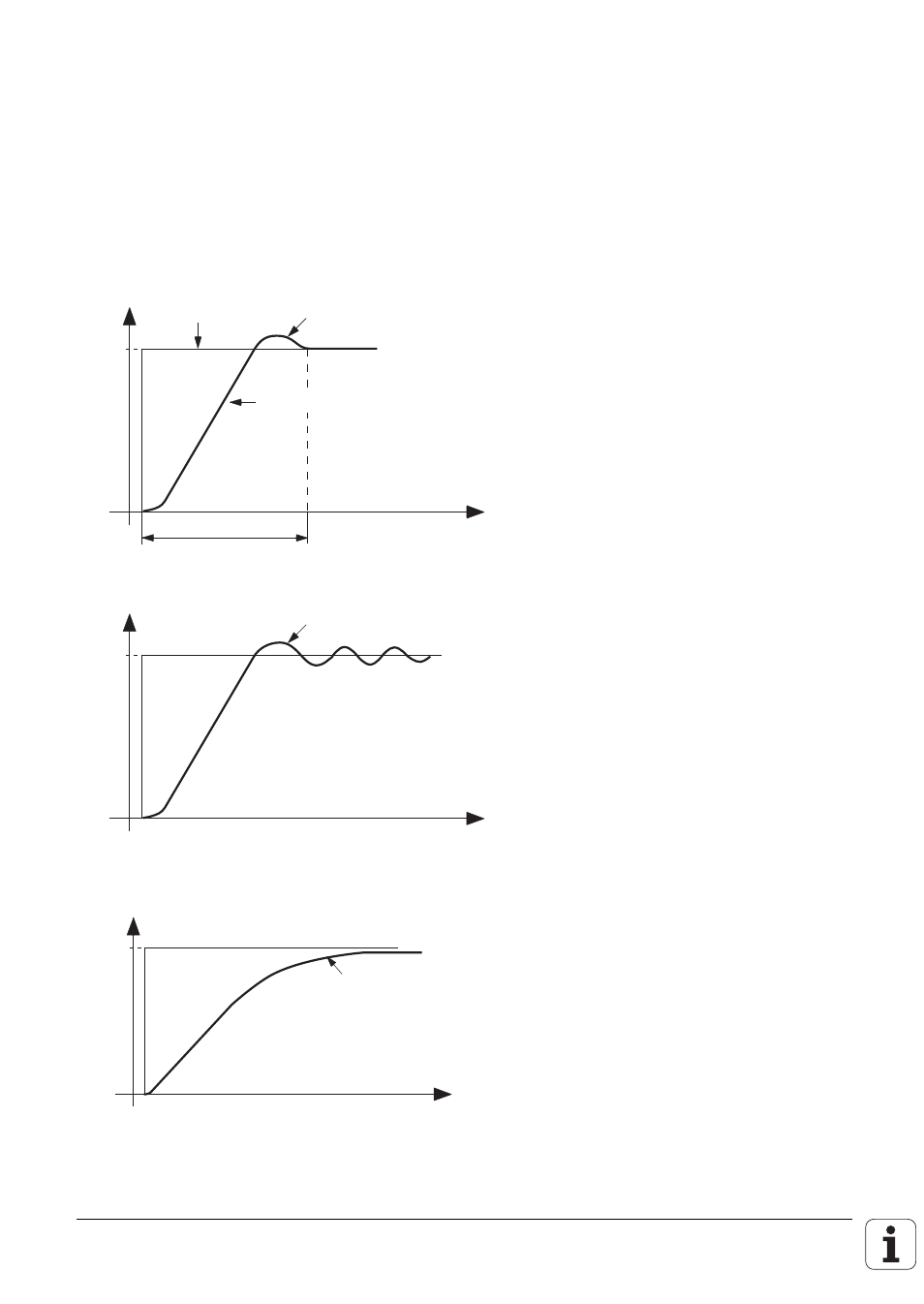
so optimized that the step response shows an overshoot. The following picture shows the ideal
response of the tacho-signal.
U [V]
t [ms]
U
max
T
Tacho-signal
1 Overshoot
Given step
function
The following pictures show incorrectly adjusted tacho-signals:
U [V]
t [ms]
U
max
Several overshoots
Incorrect!
The P-component of the subordinate control loop is too high, or the I-component too low.
U [V]
t [ms]
U
max
Incorrect!
Too flat
The P-component of the subordinate control loop is too low, or the I-component too high..