4 pin layouts, 4 data interface functions – HEIDENHAIN TNC 407 (243 020) Technical Manual User Manual
Page 664
8-17
These signals perform the same functions as those on the RS-232-C/V.24 interface.
The transmission protocol is absolutely identical for the RS-232-C/V.24 and RS-422/V.11 interfaces.
In addition, the protective earth connects the transmitter and receiver casings. The signal GND
represents the differential voltage reference conductor.
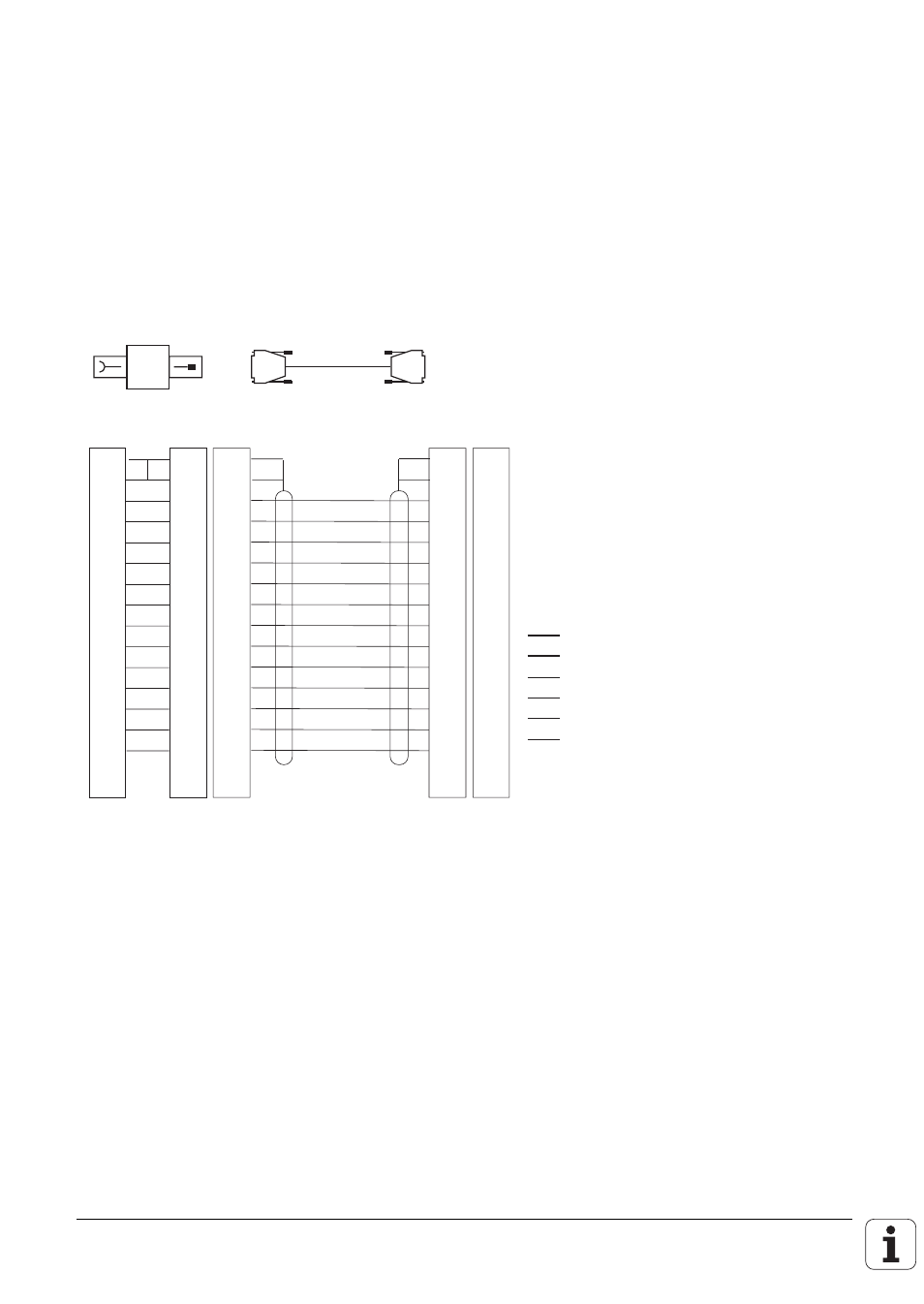
2.3.4 Pin layouts
1
2
3
4
5
6
7
8
9
10
11
12
13
14
15
1
2
3
4
5
6
7
8
9
10
11
12
13
14
15
•
•
LE
1
2
3
4
5
6
7
8
9
10
11
12
13
14
15
1
2
3
4
5
6
7
8
9
10
11
12
13
14
15
1
2
3
4
5
6
7
8
9
10
11
12
13
14
15
V.11-Adapter-Block
RS-422
Adapter block
•
•
•
•
•
bl
gr
ws
gn
ws/gn
gr/rs
sw
rt
rs
br
ge
br/gn
rt/bl
sw
BL
GND Chassis
RXD
CTS
TXD
RTS
DSR
DTR
GND Signal
RXD
CTS
TXD
RTS
DSR
DTR
BL
GY
WH
GN
WH/GN
GY/PK
BK
RD
PK
BN
YL
BN/GN
RD/BL
sw
BL
2.4
Data interface functions
The data interfaces on the TNC can be used to save data and files and read them back in again, to
output programs to external devices (e.g. printers), to read in programs and simultaneously execute
them and to carry out data transfer (communication) between TNCs.