2 plc power supply, X44 = power supply 24 v for plc – HEIDENHAIN TNC 407 (243 020) Technical Manual User Manual
Page 47
3-17
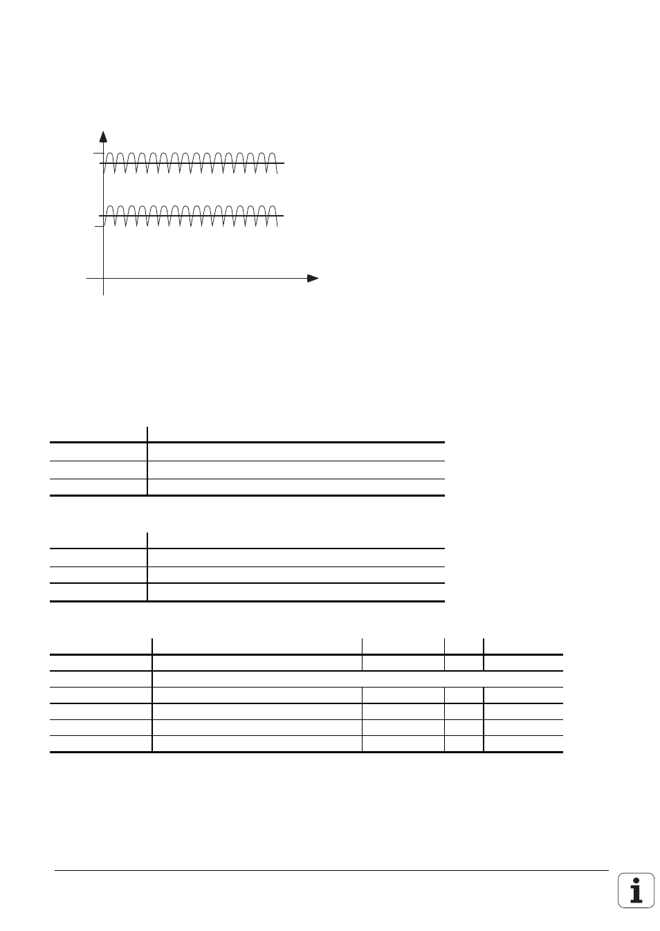
4.1.2 PLC power supply
The PLC section (PLC inputs and outputs) of the LE and PL is run from the 24 V machine control
voltage supply, generated according to VDE 0160 (base insulation). Superimposed AC components,
such as those caused by a three-phase bridge rectifier without smoothing, are permissible up to a
ripple factor of 5 % (see DIN 40110/10.75, Section 1.2).
32.6 V
31 V
20.4 V
18.5 V
U
t
The 0 V-line of the PLC-power supply must be grounded with an earth lead (
∅ ≥
6 mm
2
) to the main
frame ground of the machine. The earth lead at the frame of the PL 410 must be directly connected
to protective earth with an earth lead (
∅
≥
6mm²). To prevent ground loops, the measured voltage at
the analog inputs must not be grounded
X44 power supply for the PLC
Connection terminals
Pin Number
Assignment
1
+ 24 V
DC switched off by EMERGENCY STOP
2
+ 24 V
DC not switched off by EMERGENCY STOP
3
0 V
Power supply for the PL 400
Terminal
Assignment
X13
+24 V
DC switched off by EMERGENCY STOP
X12
0 V
X3 Pin 12
+ 24 V
DC not switched off by EMERGENCY STOP
Power supply for the PL 410
Terminal
Assignment
PL #1
or
PL #2
X9
0V
X10
+24 V logic supply and for "Control ready"
X11
+24 V supply for outputs
O32 - O39
or
O64 - O71
X12
+24 V supply for outputs
O40 - O47
or
O72 - O79
X13
+24 V supply for outputs
O48 - O55
or
O80 - O87
X14
+24 V supply for outputs
O56 - O62
or
O88 - O94
The routing and connection of the thermistors and analog inputs must be shockproof to VDE 0160
(Section 5.5.1). If this cannot be guaranteed, then both the PLC and the PL 410 must be supplied
with voltage in accordance with VDE 0160, 5.88 recommendations for low-voltage electrical
separation.