2 signal levels – HEIDENHAIN TNC 407 (243 020) Technical Manual User Manual
Page 658
8-11
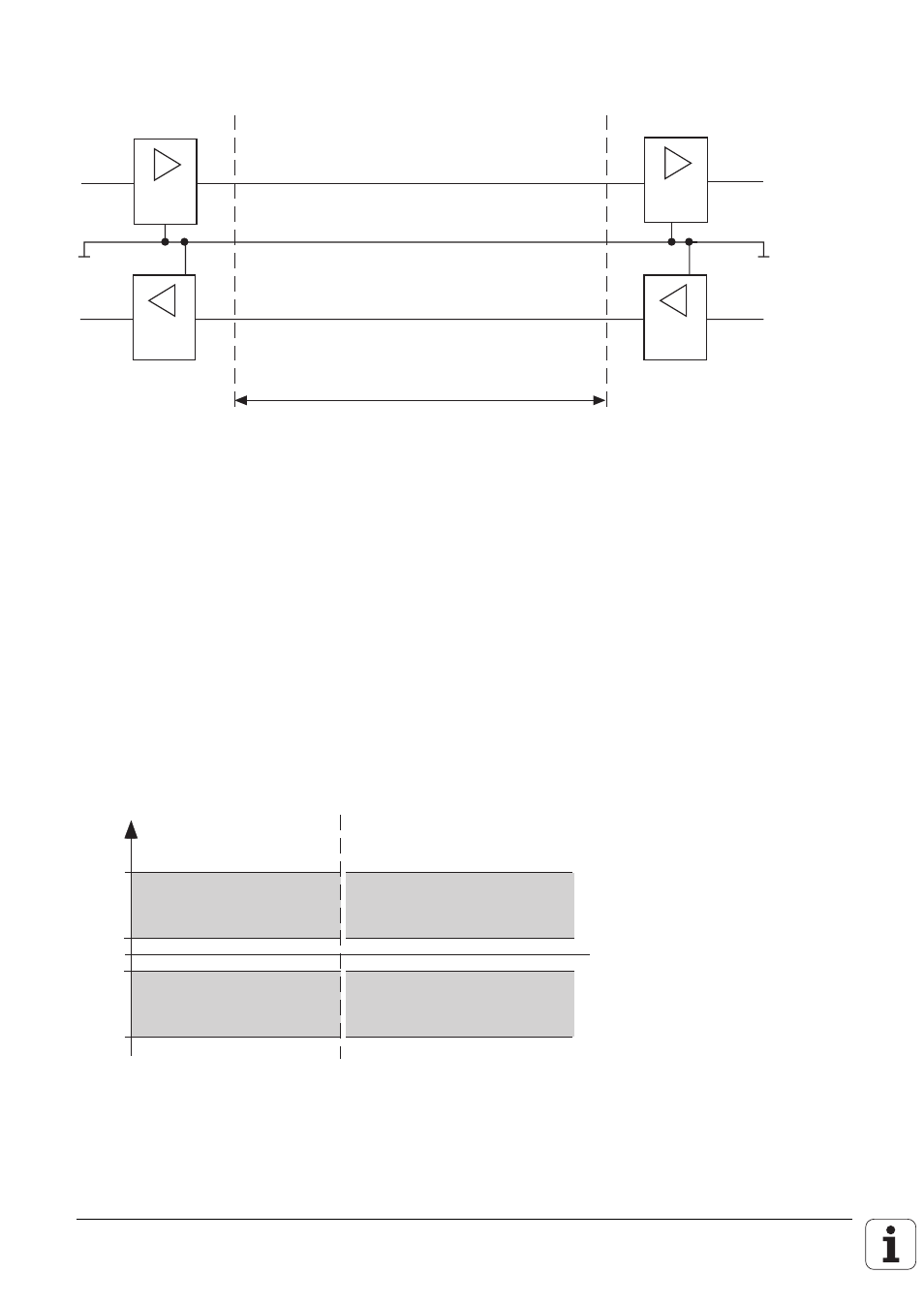
Physical connections:
Sender
Transmitter
Übertragungsstrecke
Transmission path
Empfänger
Receiver
RxD
TxD
RxD
TxD
2.2.2 Signal levels
The RS-232-C/V.24 interface must differentiate between two different signal lines and their levels.
Data lines:
The data signals are defined as being logic "1" (MARK) over the range -3V to -15V and as logic "0"
(SPACE) over the range +3V to +15V.
Control and signal lines:
These signals are defined as being ON (High) over the range +3V to +15V and as OFF (Low) over the
range from -3V to -15V.
For all of the signals, the voltage range from -3V to +3V is not defined as a logic level and can
therefore not be evaluated.
–
1
3
U [V]
+ 15
– 15
+
1
3
Datensignale
Data signals
Steuer- und Meldesignal
Control and message signal
"0"
SPACE
HIGH
ON
"1"
MARK
LOW
OFF
0