1 technical data, 1 plc inputs, 2 plc outputs – HEIDENHAIN TNC 407 (243 020) Technical Manual User Manual
Page 82
01.98
11.1 Technical data
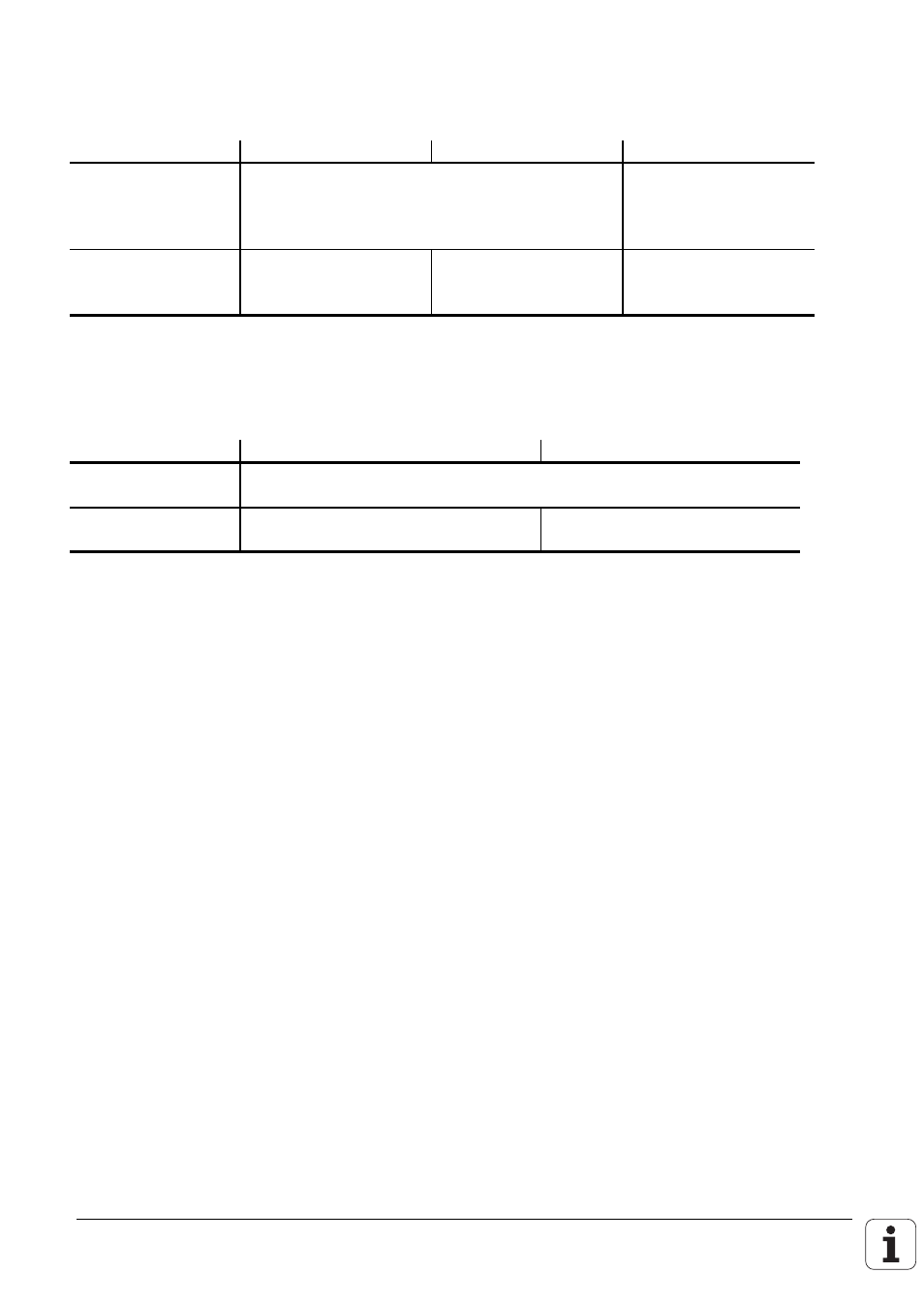
11.1.1 PLC Inputs
Logic Unit / PL 410
PL 410 B
PL 400
Voltage ranges:
"1" signal: Ui
13 V to 30.2 V
16.5 V to 30 V
"0" signal: Ui
–20 V to 3.2 V
–20 V to 4 V
Current ranges:
"1" signal: Ii
3.8 mA to 8.9 mA
2.5 mA to 6 mA
6.2 mA to 12.6 mA
"0" signal: Ii
1.0 mA at Ui=3.2 V
0,65 mA at Ui=3.2 V
1.6 mA at Ui=4 V
11.1.2 PLC Outputs
Transistor outputs with current limiter
Logic Unit
PL 400 / PL 410 / PL 410 B
Min. output voltage
for "1" signal
3 V under supply voltage
Nominal operating
current per output
0.1 A
1.2 A
Permitted load: resistive load; inductive load only with quenching diode parallel to inductance.
Not more than one output may be shorted on the logic unit at any one time.
One shorted output causes no overload.
No more than half of the PLC outputs may be driven at once (usage factor 0.5).