Power supply, Logic unit and plc i/o-board, 1 nc power supply – HEIDENHAIN TNC 407 (243 020) Technical Manual User Manual
Page 46: X31 = power supply 24 v, Dc for nc, 4 power supply 4.1 logic unit and plc i/o-board
3-16
TNC 407/TNC 415
4 Power supply
01.98
4 Power supply
4.1 Logic unit and PLC I/O-board
Supply
voltage
Voltage range
DC average
Max. current
consumption
Power
consumption
LE
NC
section
24 Vdc
2)
Lower limit
20.4 V
- - -
LE 415: 1.5 A
LE 407: 1.3 A
LE 415:
≈
36 W
LE 407:
≈
24 W
PLC
section
24 Vdc
3)
Lower limit
31 V
- - -
1)
2 A
when half of the
inputs/outputs
are switched on
simultaneously
≈
48 W
when half of the
inputs/outputs are
switched on
simultaneously
PL 410 B
Digital
inputs/out
puts
20 A
when half of the
inputs/outputs
≈
480 W
when half of the
inputs/outputs
are switched on
simultaneously
are switched on
simultaneously
Analog
inputs
24 Vdc
2)
≈
100 mA
≈
2.4 W
PA 110
24 Vdc
3)
≈
100 mA
≈
2.4 W
1)
Voltage surges up to V
- - -
for t < 100 ms are permissible.
2)
VDE 0160, 5.88 low-voltage electrical separation
3)
VDE 0160, Base insulation
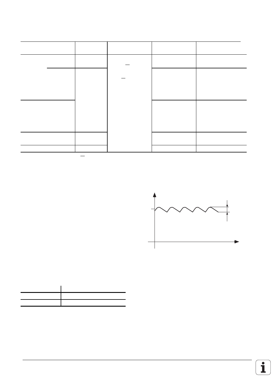
4.1.1 NC power supply
The NC section of the LE must not be supplied
from the machine control voltage supply! It
requires an individual, external and separately
generated supply voltage according to VDE
0160, 5.88 recommendations for low-voltage
separation.
Use 24 V DC with a permissible AC component
of 1.5 V
PP
(recommended filter capacitor 10 000
µ
F/40 V DC).
24 V
U
t
1.5 V
pp
X31 power supply for NC
Connection terminals
Pin Number
Assignment
1
+ 24 V DC
2
0 V