Emergency stop routine, 3 emergency stop routine – HEIDENHAIN TNC 407 (243 020) Technical Manual User Manual
Page 713
10-5
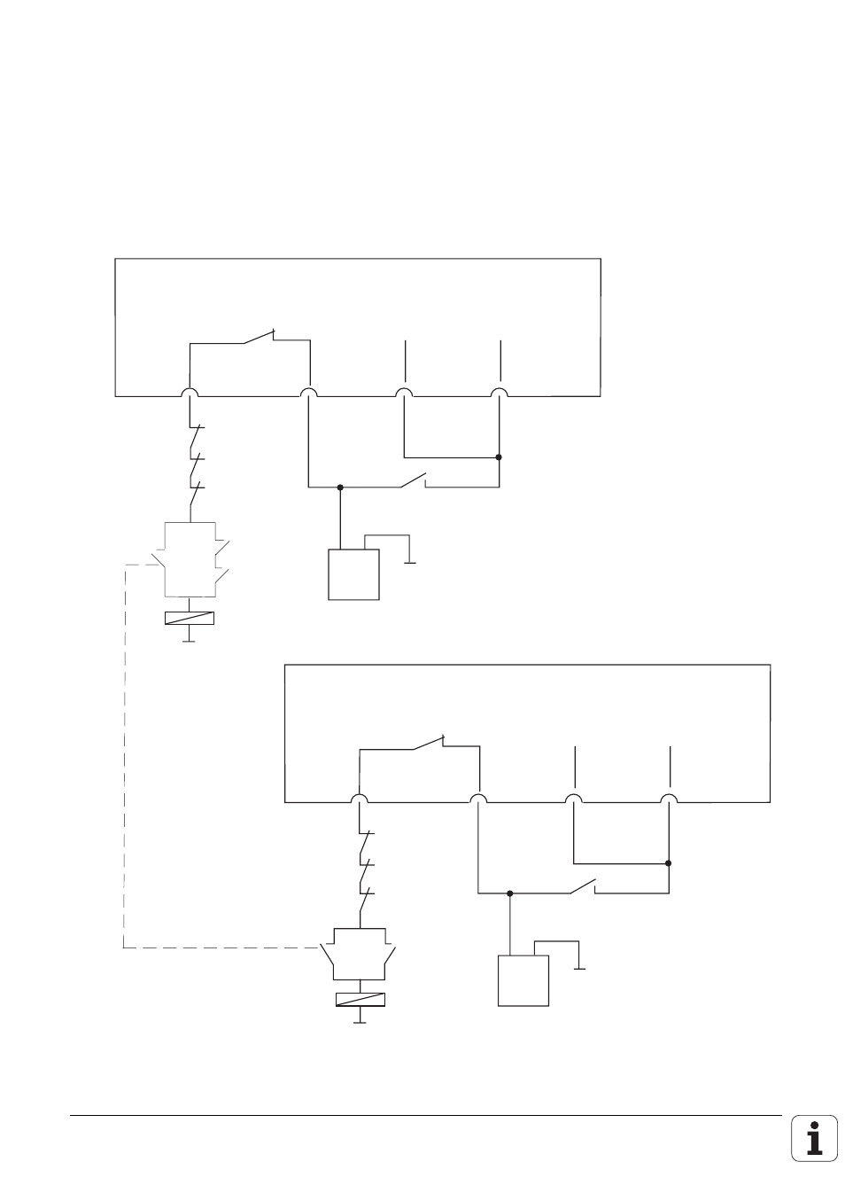
1.3 EMERGENCY STOP routine
The internal EMERGENCY STOP shutdown of the TNCs is tested when the supply voltage is
switched on, i.e. the supply voltage to each processor is turned off for a short time.
Suitable protective circuitry must be used to ensure that the positioning module is not ready for
operation if the NC test reveals an error, i.e. the voltage for the feedback is mutually interrupted.
This can be achieved by the circuit illustrated. The test starts when the control voltage is switched
on.
+ -
LE 407/415
Switch opens for a short time when control
voltage to each processor is turned on
X41/34 X44/2 X44/1 X42/4
24V not
interruptible
24V
interruptible
Feedback
"Control ready"
EMERGENCY
STOP buttons
Control
voltage
on
k1
k1
24 V
PLC
"Control is
ready"
+ -
LE 234.003
Switch opens for a short time when control
voltage to each processor is turned on
X41/34 X44/2 X44/1 X42/4
24V not
interruptible
24V
interruptible
Feedback
"Control ready"
EMERGENCY
STOP buttons
Control
voltage
on
k1
k1
K1
24 V
PLC
"Control is
ready"
k3
K1