HEIDENHAIN TNC 407 (243 020) Technical Manual User Manual
Page 727
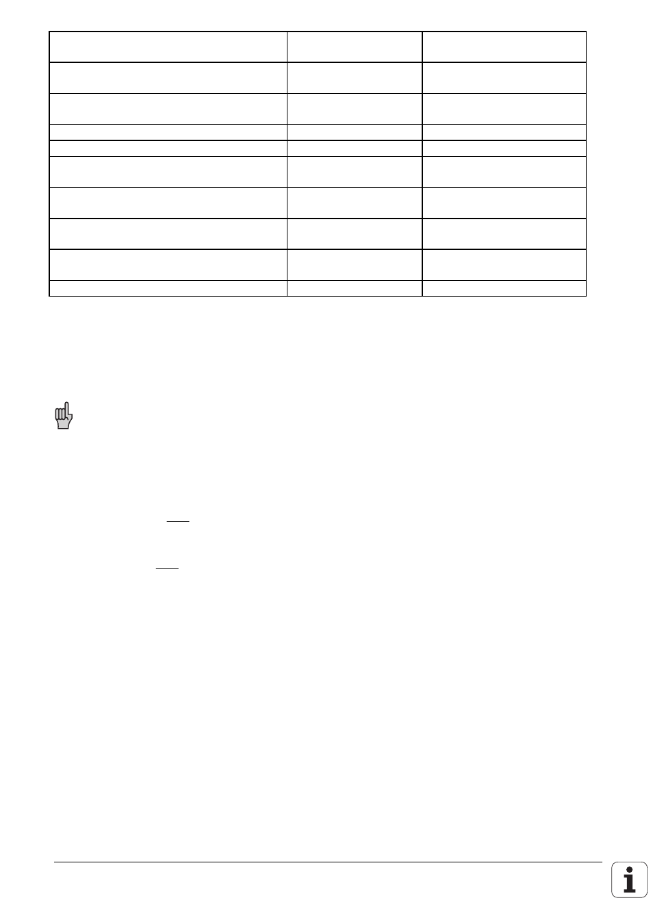
Function
MP
Provisional input value
Axis sequence when approaching
reference marks
1340.x
0
Select axes with digital speed controller
1900
Bit 0 ... 4
Monitor speed controller
1910.x
310 000
Integral component for speed controller
1920.x
5
Proportional component for speed
controller
1940.x
10
Polarity for torque signal
1950
Bit 0 ... 4
0
Select encoder for position control
1951
Bit 0 ... 4
1
Motion monitor for position and speed
1970
0 ...
0 => inactive
Delayed shutdown of position controller
1980
0
Checking polarity of nominal voltage
Cancel override and start axes with direction keys for a short period. Watch drive response, modify
polarity while turning.
The monitor via MP1910 is in effect (error message: "GROSS POSITIONING ERROR 3F "
if polarity is wrong).
Optimizing
The following curves should be displayed in the oscilloscope for each axis:
•
Nominal speed (
mm
min
) : N
NOMINAL
•
Actual speed (
mm
min
) : N
ACTUAL
•
Output analogue voltage (mV): V
ANALOGUE
A step function is output for optimizing (see "Oscilloscope", later in this chapter). The feed rate must
be selected such that the analogue voltage is < 8 V. It is now only necessary to press the
appropriate axis direction keys to output a step function to the servo amplifier.
Proportional component MP1940.x
MP1940.x is increased until the step response (actual speed) shows large control fluctuations. This
value is then halved to reduce overshoot to virtually nil.
Integral component MP1920.x
MP1920.x is then increased until large control fluctuations again occur for the actual speed. Half
this value is then entered in MP1920.x. The resulting overshoot should not exceed 40%.