3 graphics window, 1 view in three planes, 2 rotating the coordinate system – HEIDENHAIN TNC 407 (243 020) Technical Manual User Manual
Page 257: 3 blk form and datum shift

6.3 Graphics window
The simulation-graphics (TNC 407 and TNC 415) or parallel-graphics (TNC 415 only) are depicted in
the graphics window. It is possible to choose between three different graphics display modes.
With the aid of a Soft key the operator can select an additional status-display instead of the graphics
(see User's Manual). The graphics-display on the VDU-screen can be altered by machine
parameters.
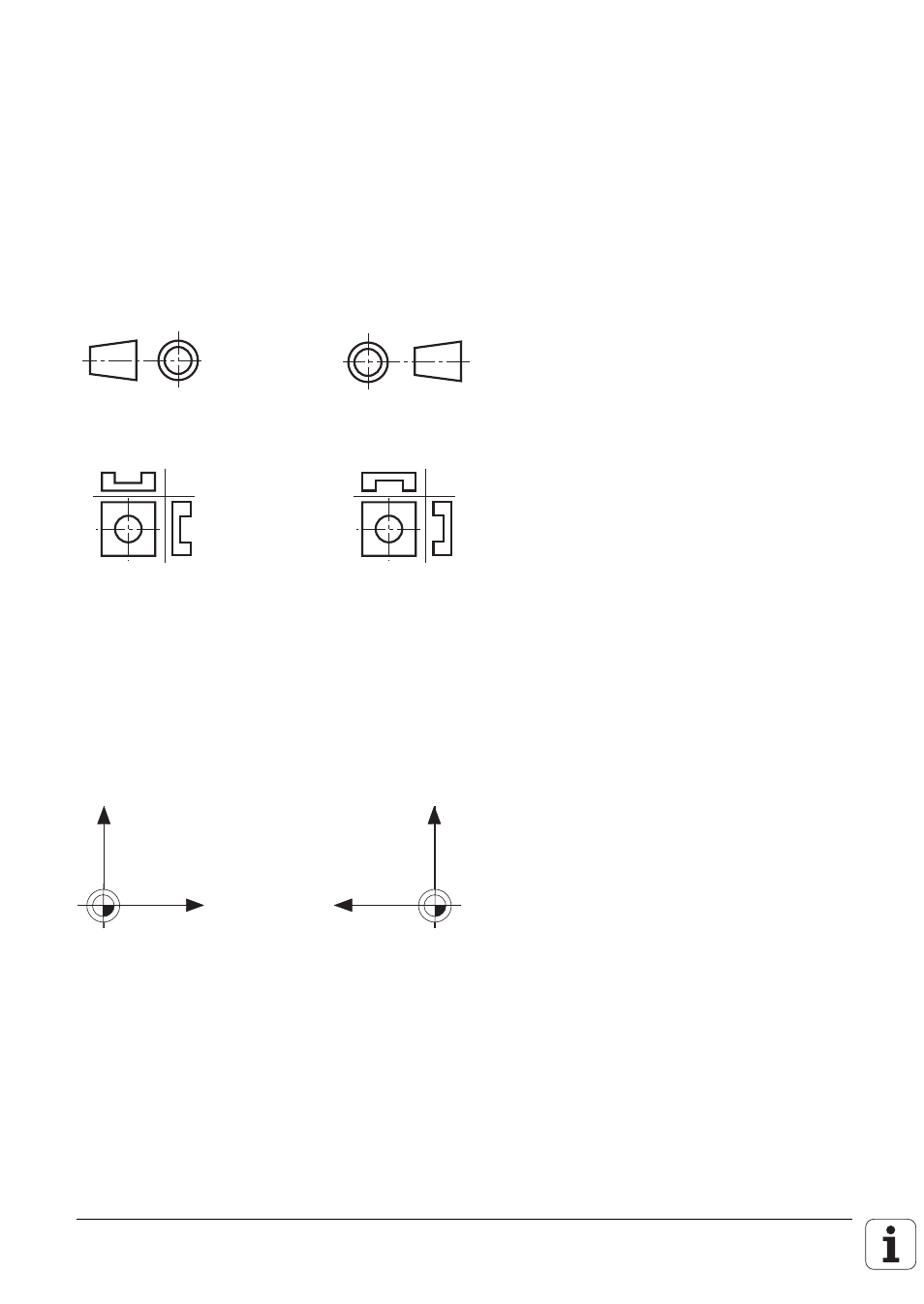
6.3.1 View in three planes
The 3-plane display mode can be produced according to either European or American convention.
German preferrred
U.S. preferred
Example
:
The cursor position can be shown in the 3-plane display mode. This function must be activated with
machine parameter MP7310, bit 3.
6.3.2 Rotating the coordinate system
The coordinate system can be rotated by +90° in the machining plane
This is useful when, for instance, the Y-axis is fixed as the tool axis.
X
Z
No rotation
90
°
rotation
Z
X
6.3.3 BLK form and datum shift
A number of BLK forms can be programmed in sequence in an NC program. Machine parameters
are used to select whether, after a Cycle 7 "Datum Shift", the definition of the next BLK form is also
shifted.
