HEIDENHAIN TNC 407 (243 020) Technical Manual User Manual
Page 63
3-33
The casing of the connection box must be electrically connected with the frame of the machine.
The 0 V of the nominal value differential input must be joined to signal ground, (cable cross-section
≥
Ø 6 mm², see also under "Earthing plan").
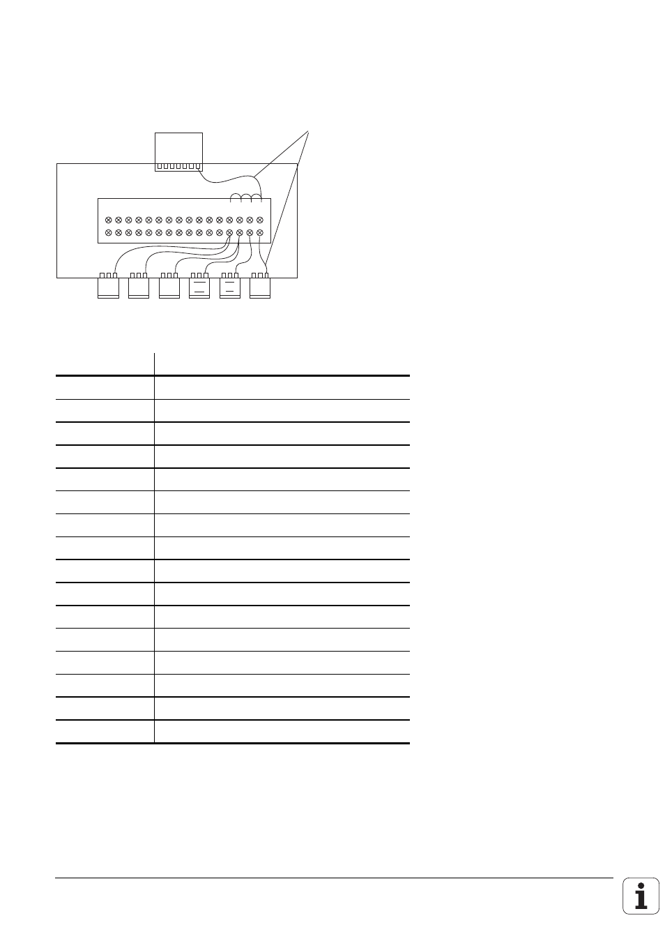
Suggested solution for connecting and wiring the screening in the connection box:
Insulated against housing
Leads are provided
with end sleeves.
Cable screens are led onto 0.14 mm
2
insulated strands via crimp eyelets.
SERVO
1 2 3 4 5 6 7 8 9 1 0 11 12 13 14 15 16
LE
•
•
X
Y
Z
S
IV
V
Pin number
Assignment
1
Nominal value output
X axis
2
Nominal value output 0 V
X axis
3
Nominal value output
Y axis
4
Nominal value output 0 V
Y axis
5
Nominal value output
Z axis
6
Nominal value output 0 V
Z axis
7
Nominal value output
IV axis
8
Nominal value output 0 V
IV axis
9
Nominal value output
V axis
10
Nominal value output 0 V
V axis
11
Nominal value output
S axis
12
Nominal value output 0 V
S axis
13
Screen connection
14
Screen connection
15
Screen connection
16
Screen connection
HEIDENHAIN recommends that the logic unit and the connection box be connected by
HEIDENHAIN-cable Id.-Nr. 290 109 ..
If the manufacturers want to use their own cable, HEIDENHAIN offers a 15 pin Sub-D connector
with solderable leads (Id.-Nr. 243 971 ZY).