4 gear change – HEIDENHAIN TNC 407 (243 020) Technical Manual User Manual
Page 225
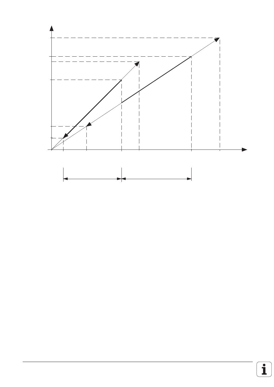
The following diagram explains the relationships:
[min
–1
]
U [V]
MP3210.1
= 8 V
MP3210.0
= 6 V
MP3240.1
= 1 V
3375
MP3515.1
1875
750
0
250
3000
MP3510.1
1500
MP3510.0
I
II
Gear range I: 1500 rpm at 6V (MP3510.0, MP3210.0)
Gear range II: 3000 rpm at 8V (MP3510.1, MP3210.1)
Upper S override limit: 125% (MP3310.0)
Lower S override limit: 50% (MP3310.1)
Max. output speed for gear range II: 3375 rpm (MP3515.1)
Minimum output voltage: 1V (MP3240.1)
4.1.4 Gear change
Gear change is controlled by the PLC-program. Up to eight gear ranges are available, coded in Word
W256. The NC enters the gear code for the gear ranges one to eight in Word W256 according to the
programmed spindle speeds in the NC-program (see MP3510).
After setting the gear-code, the marker M2043 is set by the NC as a change signal.
The spindle speed which is programmed in the NC-program as TOOL CALL S is stored in
Doubleword D356 and D756 in 1/1000 [rpm] by the NC.
If a different spindle speed (from the spindle speed fixed by the NC) is to be activated by the PLC,
the speed must be entered by the PLC in D756, this can then be activated by marker M2814 .
A different gear range from that which is selected by the NC can be activated by setting Word W256
and marker M2814 with the PLC. Word W256 remains unchanged until the next gear change signal.
Marker M2814 is reset by the NC after the gear change .
Check that the spindle speed selected by the PLC is within the spindle-speed limits of the selected
gear range.