Plc inputs/outputs, 11 plc inputs/outputs – HEIDENHAIN TNC 407 (243 020) Technical Manual User Manual
Page 81
01.98
TNC 407/TNC 415/TNC 425
11 PLC inputs/outputs
3-51
11 PLC inputs/outputs
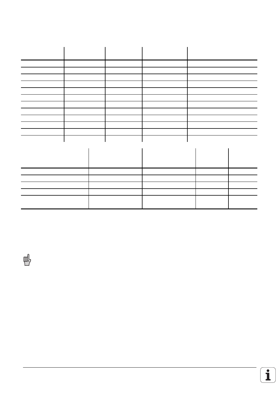
The following configurations of PLC inputs/outputs are possible with the HEIDENHAIN contouring
controls.
PLC
Inputs
PLC
Outputs
Analogue
Inputs
Thermistors
Components
56
31
--
--
LE
119
62
--
--
LE + 1 PL 400
182
93
--
--
LE + 2 PL 400
119
62
4
4
LE + 1 PL 400 + PA 110
120
62
--
--
LE + 1 PL 410 / PL 410 B
112
60
4
4
LE + 1 PL 410 / PL 410 B
184
93
--
--
LE + 2 PL 410 / PL 410 B
176
91
4
4
LE + 2 PL 410 / PL 410 B
168
89
8
8
LE + 2 PL 410 / PL 410 B
120
62
4
4
LE + 1 PL 410 + PA 110
112
60
8
8
LE + 1 PL 410 + PA 110
56
31
4
4
LE + PA 110
PL 410
PL 410 B
(Id.-Nr. 263 371 12)
PL 410
PL 410 B
(Id.-Nr. 263 371 02)
PA 110
PL 400
PLC inputs
64
56
--
63
PLC outputs
31
29
--
31
Analogue inputs
--
4
4
--
Inputs for thermistors
--
4
4
--
“Control is operational”
output
1
1
--
1
The analogue inputs of the PL 410 / PL 410 B they must be activated by a DIL switch on the PL and
a machine parameter in the TNC. When the analogue inputs are active, two outputs (O61/O62 or
O93/O94 on PL #2) and eight inputs (I120 to I127 or I248 to I255 on PL #2) of the PLC cannot be
used.
One PLC extension can be mounted on the logic unit. The second PLC extension must be
installed next to the logic unit in the switch cabinet. It is not possible to combine the
PL 410 B with the PL 410 or PA 110.