Application tab - strip till, Application tab - direct injection, General application tabs – Ag Leader InSight Ver.8.0 Users Manual User Manual
Page 236: Field notes tab, Map tab, Norac uc5 run screen environment, Boom height tab, Field notes tab map tab, More information, see, Norac uc5 r
222
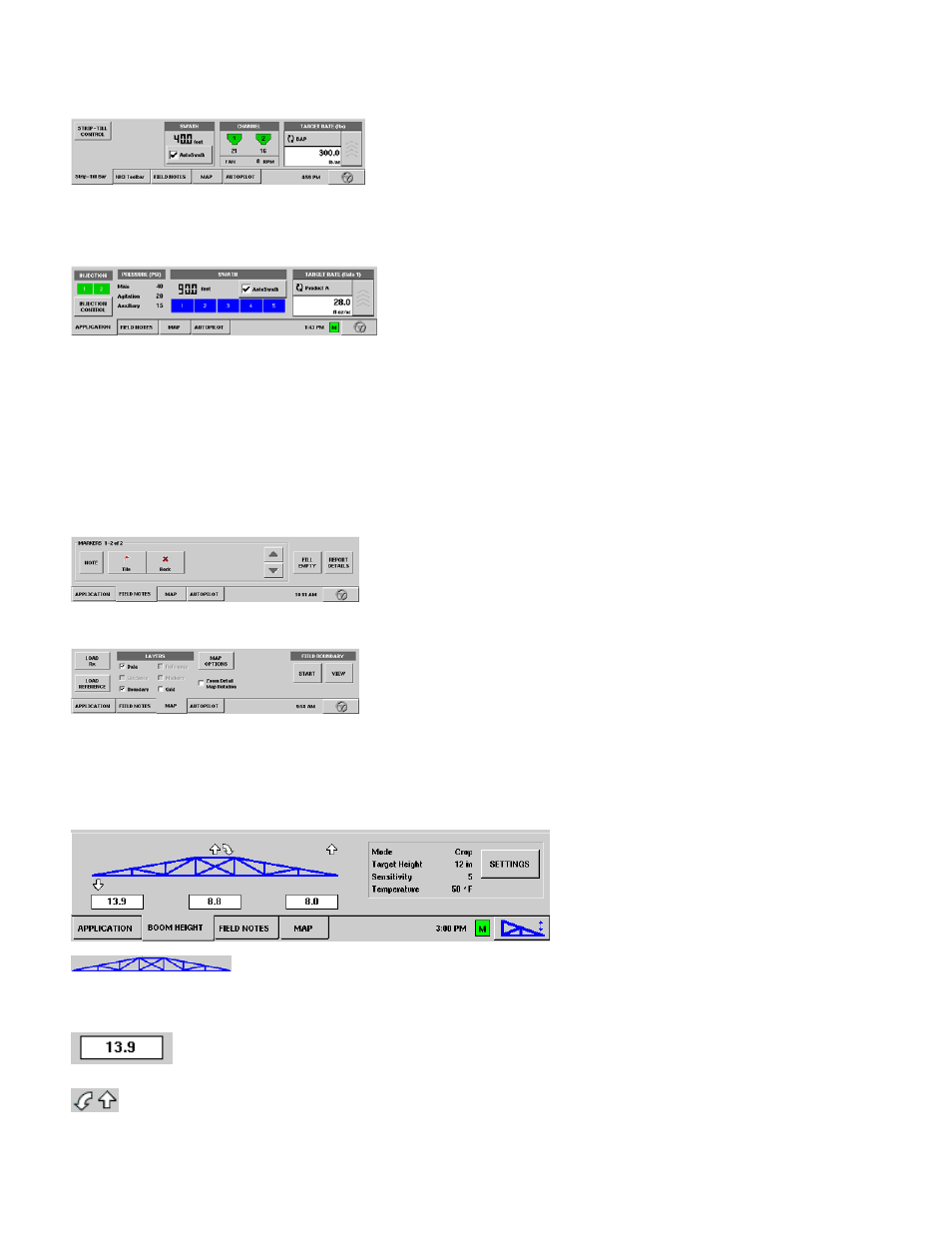
Application Tab - Strip Till
The Application Tab shown below is a typical configuration for a
Strip Till module. Because this configuration is set up to apply
multiple products, two channels are shown. (The Strip-Till
Control button is shown at the top left. For more information,
see
, and
“Strip Till Control Settings” on page
Application Tab - Direct Injection
The Application Tab shown below is a typical configuration for
a Direct Injection configuration. The Direct Injection button is
shown at bottom left; the bar displays green when the Direct
Injection pump is operating. For more information, see
Control Application Rate Tab” on page
Boom Height Tab - NORAC UC5 Spray Height Controller
“NORAC UC5 Run Screen Environment” on page
.
G
ENERAL
A
PPLICATION
T
ABS
Field Notes Tab
Map Tab
NORAC UC5 R
UN
S
CREEN
E
NVIRONMENT
B
OOM
H
EIGHT
T
AB
When the NORAC UC5 Spray Height
Controller is configured on the display,
the Boom Height Tab appears on the
Run Screen, just behind the
Application Tab.
The Boom Icon appears as blue when in Automatic Mode; and black when in
Manual Mode. The right, left and center sections appear independently on this
icon.
The numbers that appear below the Boom Icon show the distance between the boom
section and the target.
Indicates the direction that the boom section is being commanded to move. The arrows shown
around the boom appear either 1) In Automatic Mode, or 2) When the boom is in Manual Mode
and the user is manually moving the boom section.