Controller settings for hydraulic seed control – Ag Leader InSight Ver.8.0 Users Manual User Manual
Page 123
109
P
LANTING
Note: For more information regarding how to calculate the Gear Ratio, see
“Gear Ratio Calculations for Seed
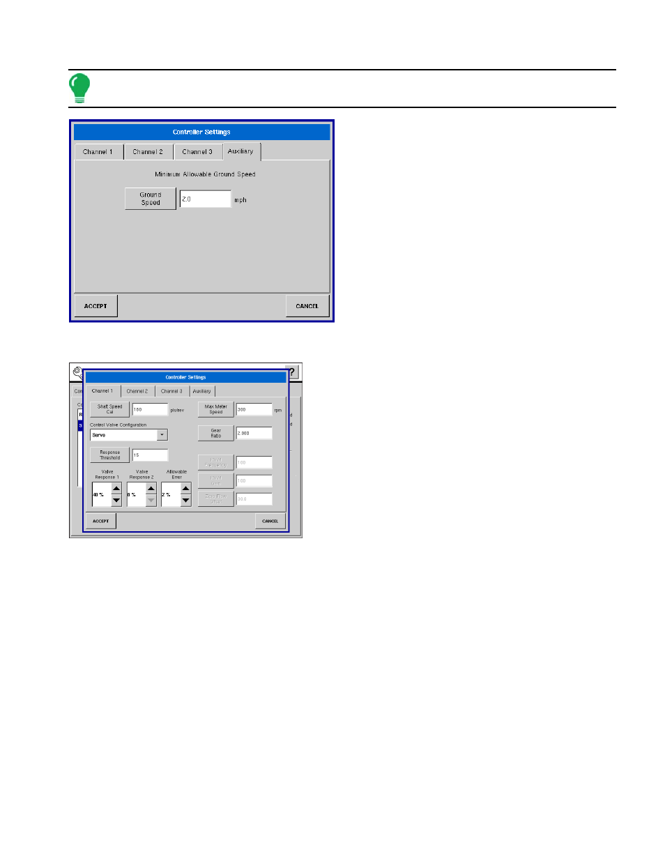
Auxiliary Tab
• Minimum Allowable Ground Speed
The display will simulate this specified ground speed
when you press the Jump Start switch. This fixed
ground speed setting compensates for delays in
acquiring an initial ground speed when starting from a
standstill.
C
ONTROLLER
S
ETTINGS FOR
H
YDRAULIC
S
EED
C
ONTROL
C
HANNEL
T
ABS
• Shaft Speed Cal
Calibration number representing the pulses that equal one
revolution of the hydraulic motor.
• Control Valve Configuration
Setting determines the type of control valve being used for the
hydraulic motor. Choices include Servo or PWM.
• Response Threshold
Determines the responsiveness to rate change.
• Valve Response 1
Determines the speed of the servo valve when product control
error exceeds the Response Threshold setting.
• Valve Response 2
Determines the speed of the servo valve when product control error is less than the Response Threshold
setting.
• Allowable Error
Determines the percent of error that is allowed prior to the product control system making any flow rate
changes.
• Max Meter Speed
Setting determines the maximum RPM of the seed meter.
• Gear Ratio
Ratio of the revolutions of the hydraulic drive motor to turn the seed meter one revolution.
• PWM Frequency
The frequency that the PWM control valve is pulsed at.
• PWM Gain