3 upward linking of symbols, 4 automatic register number allocation – Yaskawa MP940 User Manual
Page 92
3.7 Managing Symbols
3-45
3
∗
If a program is prepared using data configurations such as arrays or
indexed data, define the size to be used in the data configuration. For
example, if the data is referenced as PIDDATA_I and i varies in a range
of 0 to 9, define the size as 10.
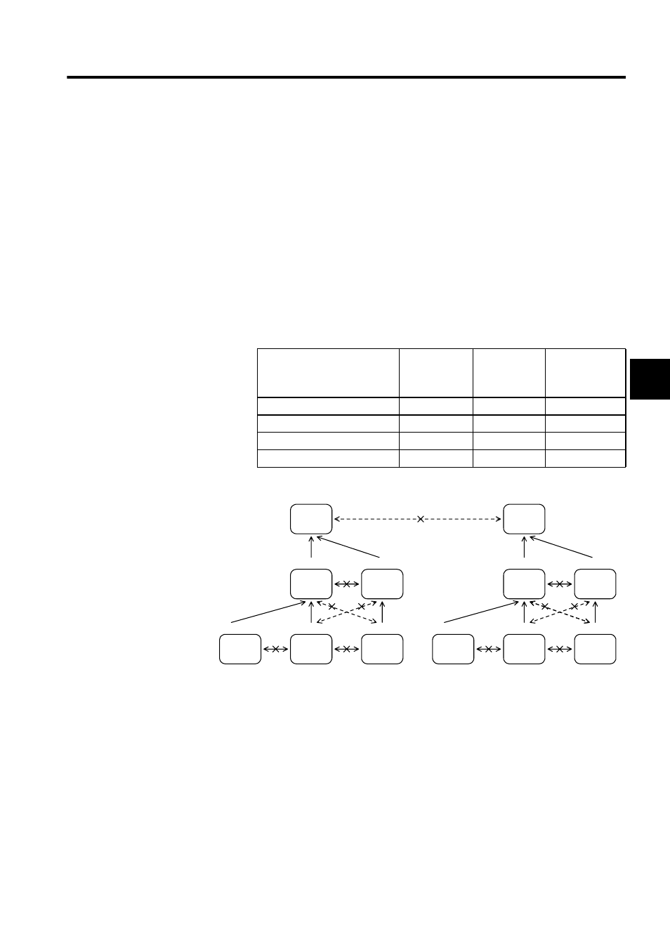
3.7.3 Upward Linking of Symbols
The following table shows the symbols that can be linked and the symbols tables that are
subject to linking. For details on the upward linking of symbols, refer to the MP9
Machine Controller User’s Manual Ladder Programming (SIEZ-C887-1.2) and the
MP9
Machine Controller User’s Manual Programming Panel Software (SIEZ-C887-2.3
(for simple operation) (To be prepared), SIEZ-C887-2.4 (for standard operation) (To be pre-
pared)).
Table 3.18 Linkable Symbols and Symbol Table for Linking
3.7.4 Automatic Register Number Allocation
The following table shows the register numbers for which automatic allocation is possible
and those for which it is not possible. For details on the automatic allocation of register num-
bers, refer to the MP9
Machine Controller User’s Manual Ladder Programming (SIEZ-
C887-1.2) and the MP9
Machine Controller User’s Manual Programming Panel Soft-
ware (SIEZ-C887-2.3 (for simple operation) (To be prepared), SIEZ-C887-2.4 (for standard
operation) (To be prepared)).
Parent
Drawing
Child Drawing
Grandchild
Drawing
Parent Drawing Symbols
No
No
No
Child Drawing Symbols
Yes
No
No
Grandchild Drawing Symbols
Yes
Yes
No
Symbols Within A Function
No
No
No
Symbol Table
Symbols
DWG H01
DWG H
DWG H02
DWG H02.01
DWG H02.03
DWG H02.01
DWG L
DWG L02
DWG L02.05
DWG L02.02
DWG L04
DWG L04.01
Grandchild
Drawings
Parent
Drawing
Child
Drawings
Symbol
Table
Symbol
Table
Symbol
Table
Symbol
Table
Symbol
Table
Symbol
Table
Symbol
Table
Symbol
Table
Symbol
Table
Symbol
Table
Symbol
Table
Symbol
Table