Yaskawa MP940 User Manual
Page 279
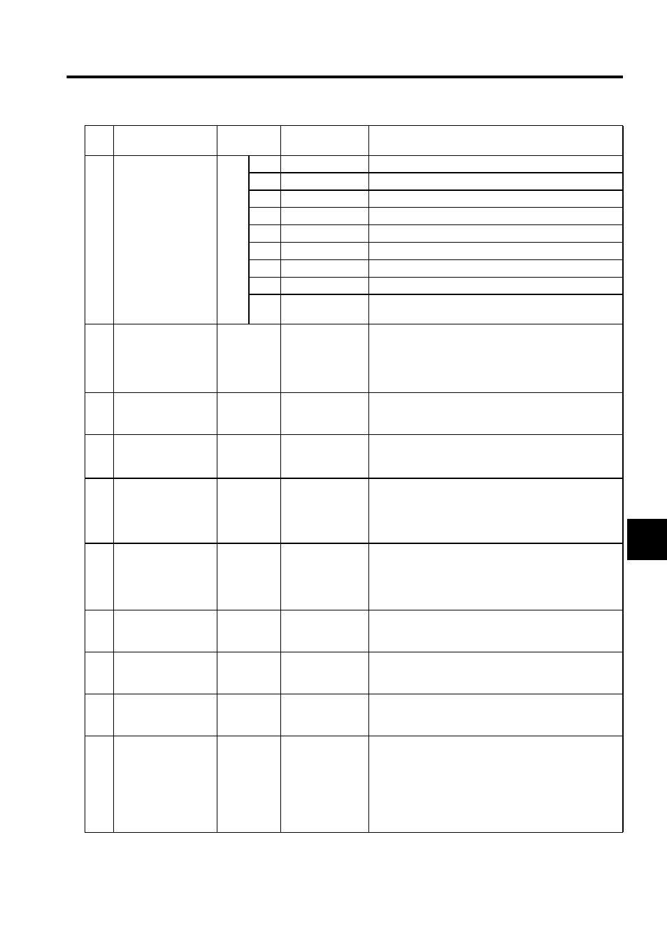
6.3 SVA Parameter Details
6-39
6
2
Servodrive Status
(SYSTS),
continued
Bit
2
V-CMP
Speed coincidence
3
TGON
Detection during monitor rotation
4
S-RDY
Servo ready
5
CLT
Torque control detection
6
VLT
Speed control detection
7
BK
Brake interlock
8
SVON
Servo ON completed
9
PON
Main circuit power ON
10 to
15
Not used.
3
Calculated Position
in Machine
Coordinate System
(CPOS)
ILC002
-2
31
to 2
31
-1
This parameter indicates the calculated position in a machine
coordinate system controlled by MP940 Modules. Normally
the position data indicated at this register is the target posi-
tion for each scan.
Refer to Supplemental Explanation.
5
Target Position
Difference Monitor
(PTGDIF)
ILC004
-2
31
to 2
31
-1
This parameter indicates the amount cleared every scan.
7
Machine Coordinate
System Latch
Position (LPOS)
ILC006
-2
31
to 2
31
-1
This parameter indicates the current position the instant the
DI latch signal turned ON.
Refer to Supplemental Explanation.
9
Machine Coordinate
System Feedback
Position
ILC008
-2
31
to 2
31
-1
This parameter indicates the current monitor position.
Note: It is not valid when an A Drawing is executed.
It is valid when an H or L Drawing is executed.
Refer to Supplemental Explanation.
11
Position Error
(PERR)
ILC00A
-2
31
to 2
31
-1
This parameter indicates the position error (number of pulses
held).
(Position error = target position - current position for each
scan). It is valid in Zero Point Return Mode, Position Con-
trol Mode, and Phase Control Mode.
13
Speed Reference
Output Monitor
(SPDREF)
IWC00C
-32768 to 32767
This parameter indicates the value output at the servo drive
as the speed reference output value.
14
Speed Monitor (NFB) IWC00D
-32768 to 32767
Reports SGDH parameter Un000: Actual Motor Rotation
Speed (r/min.) as %/number of rated rotations.
1=1%
15
Torque Monitor (TFB) IWC00E
-32768 to 32767
Reports the value of SGDH parameter: Un002 Internal
Torque Reference (%).
1=0.01%
16
Out of Range
Parameter Number
(ERNO)
IWC00F
1. Motion setting
parameter
1 to 65
2. Motion fixed
parameter
101 to 148
This parameter indicates the most recent setting parameter
number that exceeded the range in OWC000 to OWC03F
motion setting parameter or motion fixed parameter settings.
• Motion setting parameters: 1 to 65
• Motion fixed parameters: 101 to 148
When motion fixed parameters are used, the parameter indi-
cates the parameter number plus 100.
No.
Name
Register
No.
Bit Name
Description