C.3 motion monitoring parameters – Yaskawa MP940 User Manual
Page 511

Motion Parameter Tables
C.3 Motion Monitoring Parameters
C-12
C.3 Motion Monitoring Parameters
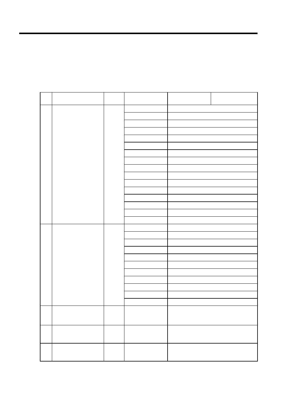
Motion monitoring parameters are parameters reported by SVA Modules. They are located
at the top of high-speed scans and are reported together. Use these parameters to control
applications and to debug user programs.
Table C.1 Motion Monitoring Parameters
No.
Name
Register
No.
Bit Name
(Setting Range)
Meaning
Remarks
1
RUN Status (RUNSTS)
IWC000
Bit 0: EOVER
Error Counter Over
Bit 1: PRMERR
Motion Setting Parameter Setting Error
Bit 2: FPRMERR
Motion Setting Parameter Setting Error
Bit 3: Not used.
Bit 4: Not used.
Bit 5: Not used.
Bit 6: Not used.
Bit 7: SVCRDY
Motion Controller RUN Ready
Bit 8: SVCRUN
Motion Controller RUN
Bit 9: DIRINV
Rotation Direction when Using Absolute Encoder
Bit 10: ABCRDC
Absolute Position Read Completed Signal
Bit 11: DIINT
DI Latch Completed Signal
Bit 12: FBPO
Feedback Pulse 0
Bit 13: POSCOMP
Positioning Completed Signal
Bit 14: Not used.
Bit 15: ZRNC
Zero Point Return Completed Signal
2
Servodriver Status
(SYSTS)
IWC001
Bit 0: ALM
Servo alarm
Bit 1: WARN
Warning
Bit 2: V-CMP
Speed conformity
Bit 3: TGON
Detection during motor rotation
Bit 4: S-RDY
Servo ready
Bit 5: CLT
Torque limit detection
Bit 6: VLT
Speed limit detection
Bit 7: BK
Brake interlock
Bit 8: SVON
Servo ON completed
Bit 9: PON
Main circuit completed
Bit10 to Bit15
Not used
3
Calculated Position in
Machine Coordinate
System (CPOS)
ILC002
-2
31
to 2
31
-1
1 = 1 pulse or 1 = 1 reference unit
1 = 1 pulse for pulse unit
Updated when the machine is locked.
5
Target Position
Difference Monitor
(PTGDIF)
ILC004
-2
31
to 2
31
-1
1 = 1 pulse or 1 = 1 reference unit
1 = 1 pulse for pulse unit
7
Machine Coordinate
System Latch Position
(LPOS)
ILC006
-2
31
to 2
31
-1
1 = 1 reference unit
(1 = 1 pulse for pulse unit)
