Output data – Yaskawa MP940 User Manual
Page 136
4.4 CNTR Function
4-43
4
• Input Data Settings
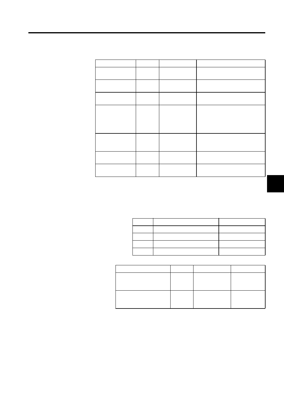
Output Data
• Operating Mode (OW0002)
The status of each bit in the operating mode register is displayed. Select the display
using the option buttons.
• Output Data Settings
Note: The register uses the default address. You can set the register address
using the Module Configuration Definition Screen.
Setting Item
Register
Range
Meaning
Number of
incremental pulses
IL0004
-2147483648 to
2147483647
1 = 1 pulse
Number of pulses within 1 scan
Hardware counter
current value
IL0006
-2147483648 to
2147483647
1 = 1 pulse
Counter’s unprocessed data
PI latch data
IL0008
-2147483648 to
2147483647
1 = 1 pulse
Counter value at latch detection
Number of
incremental pulses
after conversion
IL000A
-2147483648 to
2147483647
1 = 1 reference unit
Converted to reference units when
electronic gear is enabled.
No communications when electronic
gear is disabled.
Counter current
value
IL000C
-2147483648 to
2147483647
1 = 1 reference unit
Counter when electronic gear is
enabled.
PI latch data after
conversion
IL000E
-2147483648 to
2147483647
1 = 1 reference unit
System monitor
IL0010
-2147483648 to
2147483647
Reserved for system use
Bit No.
Command Name
Meaning
0
Count enabled
Prohibited/enabled
1
Count value preset
ON/OFF
2
Request PI latch detection
ON/OFF
3
Request coincidence detection
ON/OFF
Setting Item
Register
Range
Meaning
Count preset data
OL0004
-2147483648 to
2147483647
1 = 1 pulse
1 = 1 reference
unit
Coincidence detection
setting
OL0006
-2147483648 to
2147483647
1 = 1pulse
1 = 1 reference
unit