Phase-c pulse, Dec1 + zero signal, Dec2 + zero signal method – Yaskawa MP940 User Manual
Page 470: Dec1 + cmt + zero signal method
Motion Control
11.4.4 Zero Point Return (ZRET)
11-68
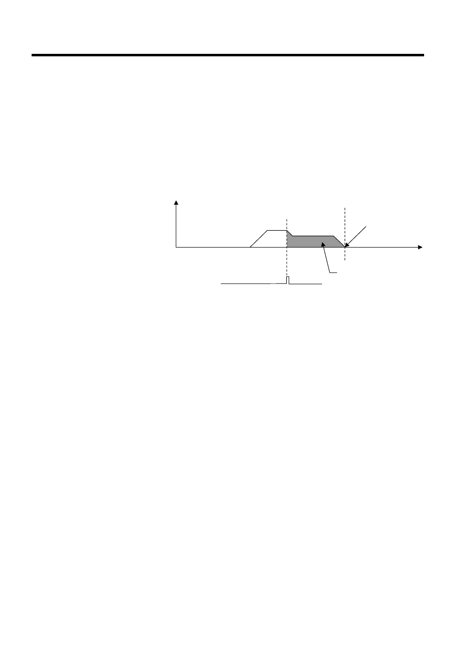
3. The axis travels at creep speed in the forward direction.
4. After the falling edge of the dog (deceleration limit switch) is detected, the axis stops
after traveling only the zero point return final travel distance from the initial zero point
signal, and that position will be the machine coordinate system zero point.
Phase-C Pulse
This method is used to perform zero point return using only a zero point signal (Phase-C
pulse) by rapid traverse using linear acceleration/deceleration.
1. The axis travels at approach speed in the direction specified in the motion setting servo
parameter (OBC0009).
2. The axis decelerates to creep speed after detecting the initial zero point signal.
3. The axis stops after traveling only the zero point return final travel distance from the ini-
tial zero point signal, and that position will be the machine coordinate system zero point.
DEC1 + ZERO Signal
Zero point return is performed using a ZERO signal (DI signal) in place of the Phase-C
pulse used in the DEC1 + Phase-C Pulse described previously.
For details, see
DEC1 + Phase-C Pulse
described previously.
DEC2 + ZERO Signal Method
Zero point return is performed using a ZERO signal (DI signal) in place of the Phase-C
pulse used in the DEC2 + Phase-C Pulse described above.
For details, see DEC2 + Phase-C Pulse.
DEC1 + CMT + ZERO Signal Method
Zero point return is performed using a ZERO signal (DI signal) in place of the Phase-C
pulse used in the DEC1 + CMT + Phase-C Pulse described above.
For details, see DEC1 + CMT + Phase-C Pulse.
0
1.
2.
3.
Reverse
Forward
← →
Zero point
Speed
reference
Creep speed
Zero point return
position
Time
Zero point return final
travel distance
Zero point signal
(Phase-C pulse)