Yaskawa MP940 User Manual
Page 290

Parameters
6.4.2 Function Selection Constants
6-50
Pn001
Function
Selection
Application
Switches 1
(Contd.)
1
Overtravel
Stop Mode
(0, 1, 2)
(Contd.)
Related Parameters
Set the following parameters to specify whether input signals
are used for overtravel or not.
• Pn50A.3: Use the P-OT input signal to prohibit forward rota-
tion.
• Pn50B.0: Use the N-OT input signal to prohibit reverse rota-
tion.
0
Speed
Torque
Position
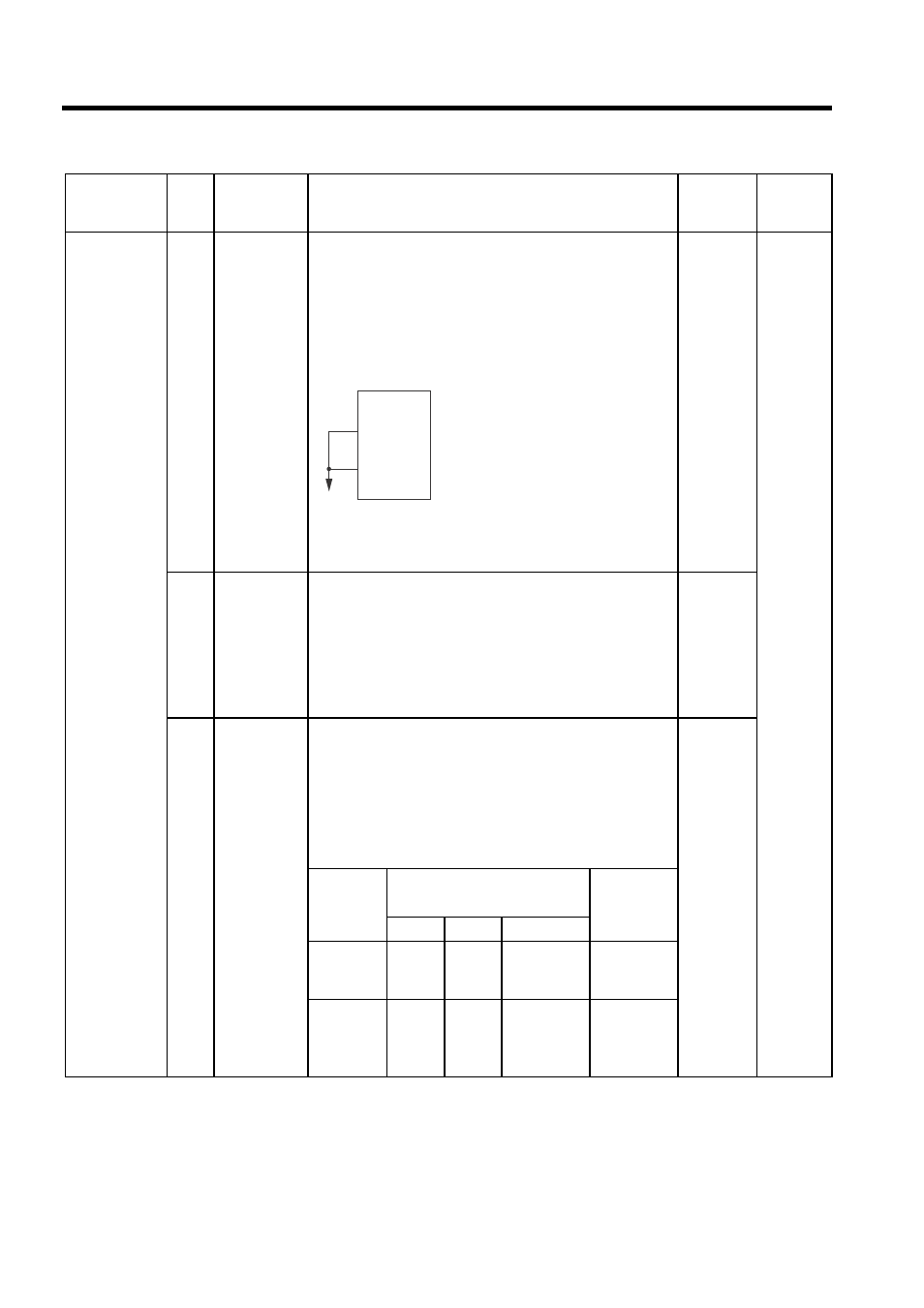
The short-circuit wiring shown in the
figure can be omitted when P-OT and
N-OT are not used.
Set the stop torque (positive input prohibit, negative input pro-
hibit) during overtravel.
• Pn406: Emergency stop torque
2
Correspon-
dance to DC
bus
(0, 1)
0: Not to use with DC bus: Input AC power supply from L1, L2
and L3 terminals.
Not compatible with DC power supply input: Input AC
power supply from L1, L2, (L3) terminals.
1: For use with DC bus: Input DC power supply from (+), 1,
−,
and (
−).
Compatible with DC power supply input: Input DC power
supply from (+), 1
−, and (−).
0
3
Warning Code
Output Selec-
tion
(0, 1)
Set if warning details are to be output using warning codes.
0: Outputs alarm codes alone for alarm codes ALO1, ALO2 and
ALO3.
1: Outputs both alarm and warning codes for alarm codes
ALO1, ALO2 and ALO3 and outputs an alarm code when an
alarm occurs.
/WARN signals: Overload and regenerative overload
The following warning codes are output in 3 bits.
0
Warning
Indication
Warning Code Output
Warning
Description
AL01
AL02
AL03
A.91
ON sig-
nal (low
level)
OFF sig-
nal (high
level)
OFF signal
(high level)
Overload
A.92
OFF sig-
nal (high
level)
ON sig-
nal (low
level)
OFF signal
(high level)
Regenera-
tive overload
Parameter No. Digit
Name
(Setting
Range)
Details
Default
Control
Modes
0 V
SERVOPACK
CN1-42
(P-OT)
CN1-43
(N-OT)
