3 i/o signal names and functions, Cn1 specifications, Input signals – Yaskawa MP940 User Manual
Page 211
5.6 SERVOPACK I/O Signals
5-39
5
CN1 Specifications
5.6.3 I/O Signal Names and Functions
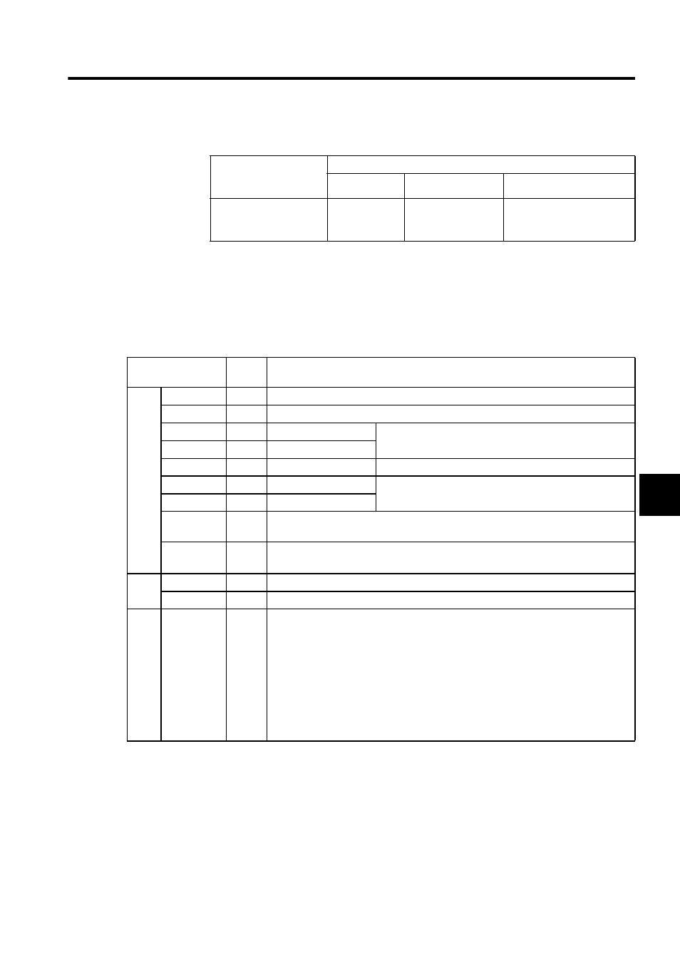
The following tables describe SERVOPACK I/O signal names and functions.
Input Signals
Note: 1. The functions allocated to /S-ON, /P-CON. P-OT, N-OT, /ALM-
RST, /P-CL, and /N-CL input signals can be changed via parame-
ters. (See 5.3.3 Input Circuit Signal Allocation of -II Series
SGMH/SGDH User’s Manual Design and Maintenance (SIE-
S800-32.2).
2. Pin numbers in parenthesis () indicate signal grounds.
3. The voltage input range for speed and torque references is a maxi-
mum of +12 V.
Specifications for
SERVOPACK
Connectors
Applicable Receptacles
Solder Type
Case
Manufacturer
10250-52A2JL or
Equivalent 50-pin Right
Angle Plug
10150-3000VE
10350-52A0-008
Manufactured by Sumitomo
3M Ltd.
Signal Name
Pin
No.
Function
Com-
mon
SIO
40
General input signal
/DEC
41
Deceleration limit switch signal for zero point return
P-OT
42
Forward Run prohibited Overtravel prohibited: Stops servomotor when movable part
travels beyond the allowable range of motion.
N-OT
43
Reverse Run prohibited
/EXT1
44
External input signal 1
General input signal.
/EXT2
45
External input signal 2
Used as latch detection signals. (If not using DI latch detec-
tion, EXT2 and EXT3 can be used as general input signals.)
/EXT3
46
External input signal 3
+24VIN
47
Control power supply input for sequence signals: Users must provide the +24-V power
supply.
BAT(+)
BAT(-)
21
22
Connecting pin for the absolute encoder backup battery.
Analog
input
V-REF
5 (6)
Used as general analog input signal.
-
9 (10)
Do not use.
7
8
11
12
15
14
3
13
18
Do not use.
Σ