User program examples example of run operation – Yaskawa MP940 User Manual
Page 411

11.2 Control Modes
11-9
11
Table 11.1 Examples of Setting Parameters
2. Select the Speed Control Mode (NCON) (bit 0 of OWC000).
3. Set the Servo ON (RUN) to ON (bit 0 of OWC001).
The speed reference will be output for the axis according to the specified motion param-
eters.
Even while the Speed Control Mode is being selected, the motion parameter settings can
be changed.
4. To stop operation, set the RUN command (RUN) and the Speed Control Mode (NCON)
to OFF.
User Program Examples
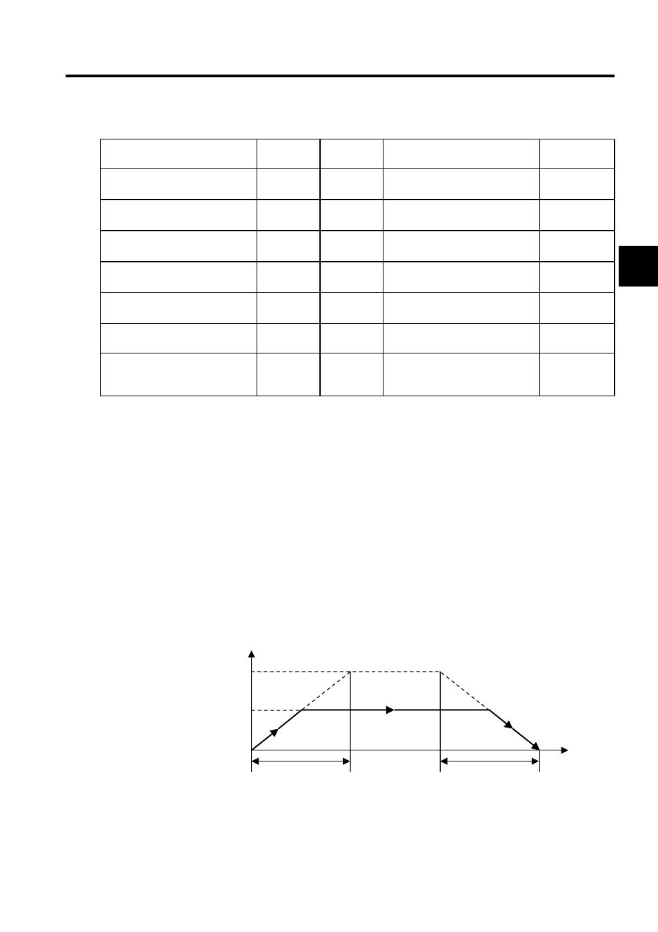
Example of RUN Operation
Fig 11.1 Speed Pattern
Name
Register No.
Setting
Range
Meaning
Setting
Example
Positive Torque Limit Setting
(TLIMP)
OWC002
-327.68 to
327.67
0.01 = 0.01%
1 = 1%
-100.00
(-100.00%)
Positive Speed Limiter Setting
(NLIMP)
OWC004
0.00 to
327.67
0.01 = 0.01%
1 = 1%
130.00
(130.00%)
Negative Speed Limiter Setting
(NLIMN)
OWC005
0.00 to
327.67
0.01 = 0.01%
1 = 1%
130.00
(130.00%)
Linear Acceleration Time
Constant (NACC)
OWC00C
0 to 32767
Linear acceleration time constant
(ms) at speed pattern generation
1000
(1 second)
Linear Deceleration Time
Constant (NDEC)
OWC00D
0 to 32767
Linear deceleration time constant
(ms) at speed pattern generation
1000
(1 second)
Filter Time Constant Setting
(NNUM)
OWC014
0 to 255
For simple S-curve acceleration
0
Speed Reference Setting (NREF)
OWC015
-327.68 to
327.67
Speed reference value
0.01 = 0.01%
1 = 1%
50.00
(50.00%)
NR
(
100%)
NREF
(
50%)
0
NACC
NACC
Speed
(%)
Speed reference
1 second
1 second
Time
(t)
