Yaskawa MP940 User Manual
Page 422
Motion Control
11.2.4 Phase Control Mode
11-20
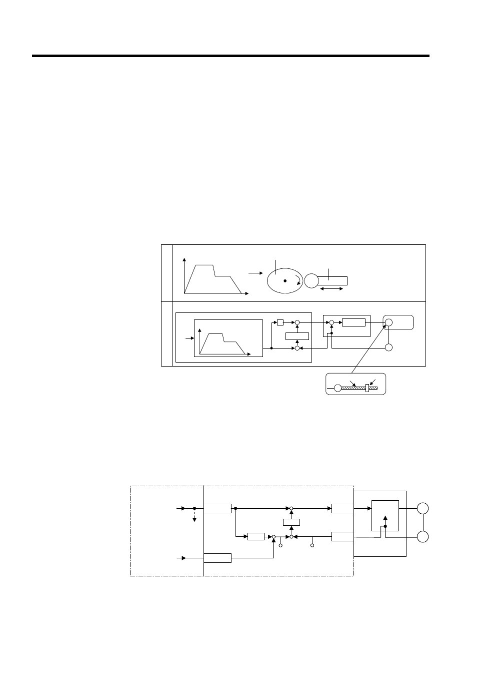
User Program Example 2: Electronic Cam
Example of RUN Operation
Cams are one of the conventional methods for changing a rotational movement to a linear
movement, and they are used to obtain the desired operation curve (displacement drawing)
during a cycle.
• A mechanical cam forms a cam with a shape corresponding to this displacement draw-
ing. Placing a follower on the circumference and rotating the cam enables the desired
linear operation to be obtained.
• An electronic cam holds the actual displacement drawing data in the controller as a posi-
tion pattern, and performs regular position control for the so-called continuous path
(CP) by changing the phase.
An electronic cam control loop can be configured using phase control. With normal phase
control, the position reference is generated by integrating the reference speed reference into
the SVA Module (see Fig. 11.11).
An electronic cam control loop cuts the integral circuit of the reference speed reference, and
provides the position reference from the phase compensation settings (see Fig. 11.12).
The following illustration shows a block diagram of a phase control loop.
Fig 11.11 Block Diagram of Phase Control Loop
S
Xref
+
+
+
-
+
-
M
PG
M
MP920
Mechanical cam
Follower
displacement
Phase
θ
Mechanical cam
Follower
When the mechanical
cam rotates, the fol-
lower moves linearly, as
shown in the displace-
ment drawing.
Electr
onic cam
P
hase ref
e
ren
ce
θ
Follower
displacement
Displacement pattern generation
Position
control
Speed
control
Servo-
motor
Encoder
Ball screw
Follower
MP940
SGDH
OWCO15
PI
OLCO16
NREF
PHBIAS
M
PG
+
±
ε
+
-
+
+
CPOS
ILC002
APOS
ILC008
CPU Module
Standard
speed refer-
ence setting
To other
machine
Position com-
pensation
setting
SVA Module
Integration
Speed refer-
ence
Counter
Speed
control