2 basic troubleshooting flow, 3 indicator errors, Led indicators – Yaskawa MP940 User Manual
Page 348
9.1 Overview of Troubleshooting
9-3
9
9.1.2 Basic Troubleshooting Flow
When a problem occurs, it is important to determine the cause and treat the problem fast to
get the system up and running as quickly as possible. The following table shows the basic
troubleshooting flow.
9.1.3 Indicator Errors
Error details can be checked by the status of indicators on the front of the MP940 Module.
In the process, we narrow down the repair location in a program by getting an overview of
the error from indicators, checking the contents of the system (S) registers, examining the
drawing or function number that caused the error and then getting an overview of operation
error details.
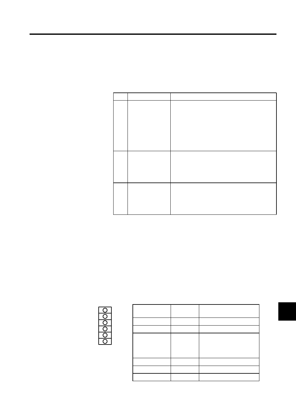
LED Indicators
The following indicators show operating status and error details for the MP940.
No.
Point
Basic Details Examined
1
Visual Check
• Equipment operation (status while stopped)
• Power ON/OFF
• I/O equipment status
• Wiring status
• Status of indicators (indicators on all Modules)
• Status of all switches (DIP switches and other
switches)
• Parameters and program content check
2
Error Check
Observe whether the following alters the error in any
way.
• Stopping the Controller.
• Resetting the alarm.
• Turning power OFF and ON.
3
Narrowing the
Range
Consider possible failure locations based on the results
of 1 and 2 above.
• Is the problem in the Controller or external?
• Is the problem in sequence control or motion control?
• Is the problem software or hardware?
Indicator Name
Indicator
Color
Meaning when Lit or
Flashing
RDY
Green
System operating normally.
RUN
Green
User program running.
ALM
Red
Lit: Minor system failure
occurred.
Flashing: System fault or fail-
ure occurred.
BAT
Red
Replace the battery.
PRT1
Green
Port 1 sending.
PRT2
Green
Port 2 sending.
RDY
RUN
ALM
BAT
PRT1
PRT2