Yaskawa MP940 User Manual
Page 313
6.4 Parameters for SGDH SERVOPACK
6-73
6
Note: 1. When more than one signal is allocated to the same output circuit,
data is output using OR logic.
2. Depending on the control mode, undetected signals are treated as
OFF. For example, in the speed control mode, the /COIN signal is
treated as OFF.
3. Types of /WARN signals: Overload, regenerative overload, and
option warning.
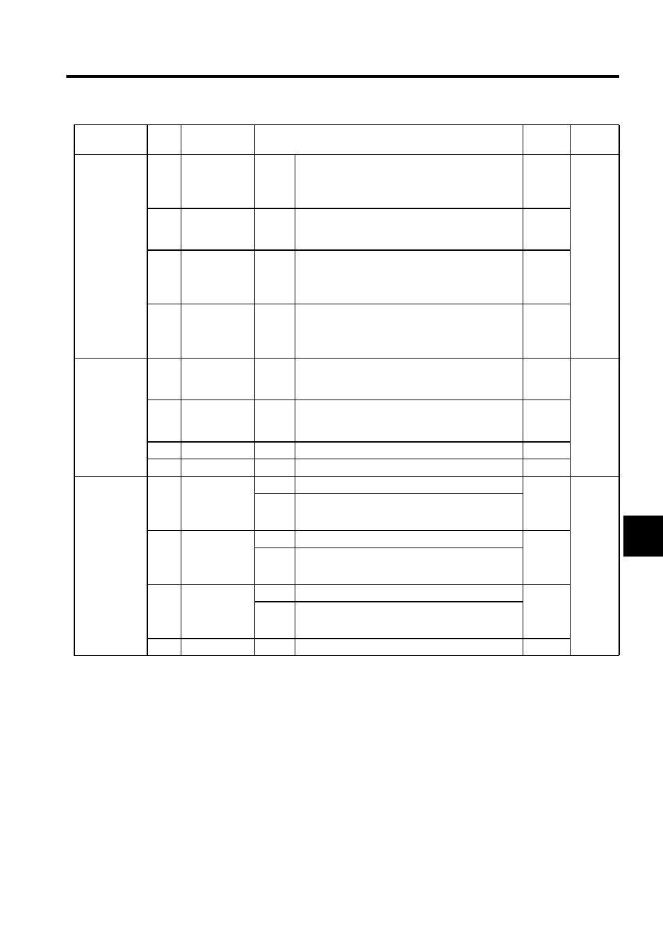
Pn50F
0
Torque Limit
Detection Sig-
nal Mapping
(/CLT)
0 to 3
Same as above.
0: Not
used
Speed
Torque
Position
1
Speed Control
Signal Mapping
(/VLT)
0 to 3
Same as above.
0: Not
used
2
Brake Inter-
lock Signal
Mapping
(/BK)
0 to 3
Same as above.
0: Not
used
3
Warning Signal
Mapping
(/WARN)
0 to 3
Same as above.
0: Not
used
Pn510
0
/NEAR Signal
Mapping
(/NEAR)
0 to 3
Same as above.
0: Not
used
Speed
Torque
Position
1
Resemble C-
signal Mapping
(/C-PULS)
0 to 3
Same as above.
0: Not
used
2
Reserved
-
-
0
3
Reserved
-
-
0
Pn512
0
Output Signal
Reversal for
SO1 (CN1-25
and 26)
0
Output signal is not reversed.
0: Not
reversed
Speed
Torque
Position
1
Output signal is reversed.
1
Output Signal
Reversal for
SO2 (CN1-27
and 28)
0
Output signal is not reversed.
0: Not
reversed
1
Output signal is reversed.
2
Output Signal
Reversal for
SO3 (CN1-29
and 30)
0
Output signal is not reversed.
0: Not
reversed
1
Output signal is reversed.
3
Reserved
-
-
0
Parameter No. Digit
Name (Setting
Range)
Contents
Default
Control
Modes