Led 2 indicators, Battery connector, Dip switch – Yaskawa MP940 User Manual
Page 177

5.2 Part Names
5-5
5
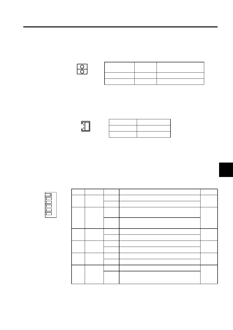
LED 2 Indicators
LED2 indicators show the MECHATROLINK’s status.
Battery Connector
Connects a battery to back up the contents of program memory.
• Connector model: DF3-2P-2DS (HIROSE)
• Battery: ER6VLY+DF3.CONNECTOR
DIP Switch
The DIP switch consists of six pins. The pins are numbered from 1 to 6, as shown in the dia-
gram with the following table.
Each pin turns ON when it is moved to the right.
Pin settings are enabled the next time the power supply is turned ON.
The function of each pin is given in the following table.
Name
Indicator
Color
Meaning when Lit
TX
Green
Sending data.
RX
Green
Receiving data.
TX
RX
Terminal Name
Function
BAT IN
Battery input
GND
Terminal ground
BAT
Pin
Name
Setting
Function
Default
6
RUN
ON
Program executed.
ON
OFF
Program stopped.
5
INIT
ON
Pin 4 OFF:
ON: Memory cleared.
OFF
OFF
Pin 4 OFF: Normal
ON: Setting prohibited
4
TEST
ON
Terminal mode/initialization mode
OFF
OFF
Online
3
FLASH
ON
Program copied from flash memory to RAM.
OFF
OFF
Program not copied from flash memory to RAM.
2
PP
ON
Use defaults for serial port 1.
OFF
OFF
Use memory settings.
1
COPY
(Valid
when pin 3
is ON)
ON
Copying M-register from flash memory enabled.
OFF
OFF
Copying M-register from flash memory disabled.
6
5
4
3
2
1
ON
RUN
INIT
TEST
FLASH
PP
COPY
