5 reversible counter mode, 6 coincidence output and interrupt functions – Yaskawa MP940 User Manual
Page 127
MP940 Functions
4.4.5 Reversible Counter Mode
4-34
4.4.5 Reversible Counter Mode
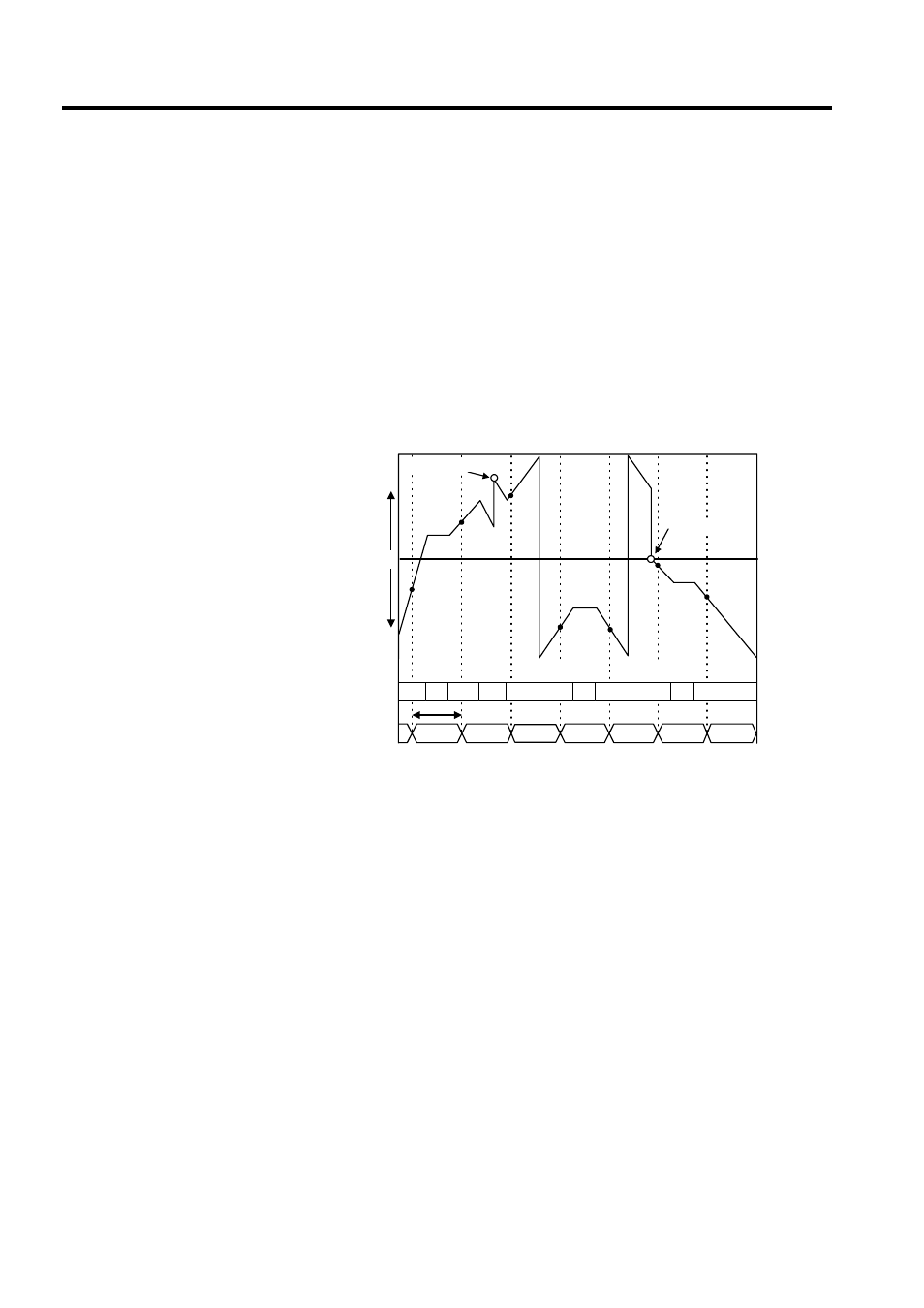
In Reversible Counter Mode, the count goes up or down according to A/B pulse inputs.
The following functions are available in Reversible Counter Mode depending on the output
register designation.
• Count Prohibit: The counter is disabled from counting.
• Count Value Preset: The count value is forcibly changed.
• PI Latch Detection: Counter values at the time of external signal inputs are stored in
memory.
• Coincidence Detection: Outputs an external output signal when the output register coin-
cidence detection set value matches the counter present value.
∗ 1.
Count present value = Hardware counter (ILxxxx+4)
∗ 2.
Count preset = Count preset data (OLxxxx+2)
4.4.6 Coincidence Output and Interrupt Functions
With the coincidence output and interrupt functions, an external output signal (coincidence
detection signal) is output when a preset output register (Coincidence Detection Set Value:
OL0006) matches the counter present value, and an interrupt signal is output to the CPU
Module.
The coincidence output function is enabled by a setting in fixed parameter 6 (Coincident
Detection).
The coincidence interrupt function is enabled by a further setting in fixed parameter 7 (Coin-
cident IRQ).
n1
n2
n3
n4
n5
n6
n7
n1
n2
n3
n4
n5
n6
n7
MIN
(80000000H)
MIN
(80000000H)
UP
UP
DOWN
UP
DOWN
DOWN
Ts
0
(+)
(-)
MAX (7FFFFFFFH)
MAX (7FFFFFFFH)
Counte
r’
s cou
nt register
Count preset *2
Count preset *2
A and B pulses
Stop
Stop
Stop
Count present value *1
Ts: Scan setting