Yaskawa MP940 User Manual
Page 112
4.2 Serial Communications Function
4-19
4
Serial Interface
RS-232C for CIR#01, and RS-485/422 for CIR#02
Only 1 stop bit for CIR#02.
Transmission Mode
• RTU: Specifies RTU Mode for MEMOBUS protocol.
• ASCII: Specifies ASCII Mode for MEMOBUS protocol.
• None: For MELSEC or no-protocol.
Transmission Delay
When the transmission delay is designated, a delay time of 1 to 100 ms is set for the start of
data transmission.
• Master: The delay time from when the MSG-SND function is executed until the com-
mand is sent.
• Slave: The delay time from when the MSG-RCV function receives the command until
the response is sent.
Automatic Response
This is the set range for relays, registers, and coils that are used for sending automatic
response messages when requests are received from the master. Therefore, it is enabled for
slaves.
Automatic response does not need to be set when there are no messages to be transferred
between the master and slaves. If the MSG-RCV function is already being used in a ladder
program to send response messages, then turn OFF the automatic reception so that process-
ing is not duplicated.
As the system default, response messages are sent within the set ranges for the parameters
from here onwards.
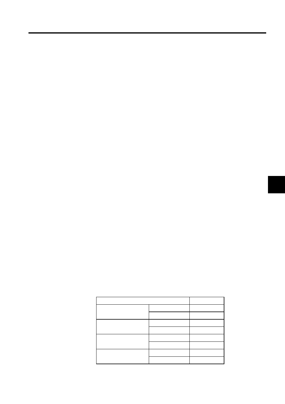
Leading Register Number and Number of Words
The following table shows the leading register numbers and the number of words.
Item
MP940
Input Relay Read
Leading register
IW0000
No. of words
2,048
Input Register Read
Leading register
IW0000
No. of words
2,048
Coil Read/Write
Leading register
MW00000
No. of words
32,768
Holding Register Read/
Write
Leading register
MW00000
No. of words
32,768