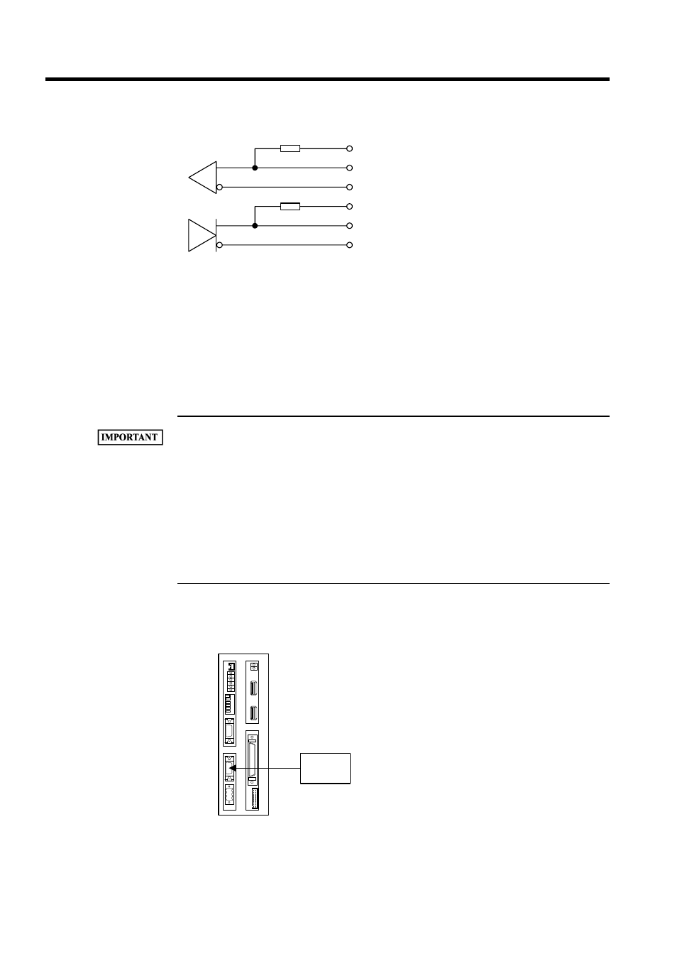
Rs-422 connection example – Yaskawa MP940 User Manual
Page 192

System Startup
5.3.3 Serial Port Connector Pin Arrangements and I/O Circuits
5-20
To connect terminating resistance, connect it to signals RXR and
RX( ), and signals TXR and TX( ) as described in the diagram. If
no connect resistance is terminating, open signals RXR and TXR.
• Module connector: 10214-52A2JL (3M)
• Cable connector: 10114-3000VE (3M)
• Shell: 10314-52A0-008 (3M)
RS-422/485 Interface Cable
• Be sure to separate the interface cable from the power system, control system, power supply system,
and other transmission systems.
• The RS-422/485 interface of the MP940 Interface Module is MDR-14 pin (CN3).
• The maximum cable length of RS-422/485 is 300 m. Use a cable as short as possible.
• The RS-422/485 interface of the MP940 is not insulated. Noise from the terminal to be connected
may cause a malfunction of the MP940. Use shielded cables or a modem to reduce the noise if nec-
essary.
• When using RS-422, insert terminating resistance if necessary. Termination must be made at the
receiving end.
• When using RS-485, add terminating resistance to both ends of the transmission line.
RS-422 Connection Example
RXR
RX(+)
RX(-)
TXR
TX(+)
TX(-)
7
3,10
4,6
11
1,8
2,9
Terminator
–
–
BAT
RDY
RUN
ALM
BAT
PRT1
6
5
4
3
2
1
NO
→
PRT2
RUN
INIT
TEST
FLASH
PP
COPY
PORT1
PORT2
POWER
+24V
GND
FG
LED
I/O
TX
R
X
1
2
M
E
C
H
A
T
R
O
L
I
N
K
MP940
MP940
Terminal
device
(PLC, etc.)
