3 gain-related parameters – Yaskawa MP940 User Manual
Page 293

6.4 Parameters for SGDH SERVOPACK
6-53
6
6.4.3 Gain-related Parameters
Table 6.5 Gain-related Parameter Table
Parameter No. Digit
Name
(Setting
Range)
Details
Default
Control
Modes
Pn100
Speed Loop Gain
Hz
1 to 2000
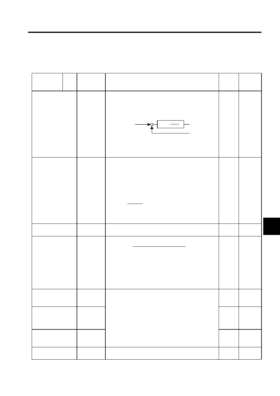
This parameter determines speed loop responsiveness set within
a range so that the machine does not vibrate.
The greater the value, the more responsive speed control will be,
but this is limited by the characteristics of the function.
Speed loop gain Kv is adjusted in 1-Hz increments provided that
Pn103: Inertia Ratio is set correctly.
For inertia ratio details, refer to Pn103 Inertia Ratio.
40
Speed
Torque
Position
Pn101
Speed Loop Integral
Time Constant
0.01ms
15 to 51200
The speed loop has an integral component to respond even to
very small inputs. This integral component is delayed for the
servo system, so the greater the time constant, the greater the
positioning adjustment time, thereby worsening response. If load
moment of inertia is great or the machine system includes vibra-
tional components, the machine will vibrate unless the integral
time constant is quite large. Use the following as a guideline.
Ti: Integral time constant (S)
Kv: Speed loop gain (value calculated using 1. above) [Hz]
2000
Speed
Torque
Position
Pn102
Position Loop Gain
1/s
1 to 2000
Do not set or use this parameter. Set the gain using SVA setting
parameter OWC010:Position Loop Gain.
40
Position
Pn103
Inertia Ratio
%
0 to 10000
The load moment of inertia of the SERVOPACK converted on
the basis of the motor shaft is factory-set to the rotor moment of
inertia of the Servomotor. Therefore, obtain the inertia ratio from
the above formula and set parameter Pn103 properly.
The above parameters are automatically set by the autotuning
operation.
0
Speed
Torque
Position
Pn104
No. 2 Speed Loop
Gain
Hz
1 to 2000
You can switch between using Pn100 to Pn102 or Pn104 to
Pn106 for speed loop gain, speed loop integral time constant,
and position loop gain, using MP940 setting parameter G-SEL
reference (Gain switching OBC0012).
OBC0012 =0: Use Pn100 to Pn102
=1: Use Pn104 to Pn106
40
Speed
Torque
Position
Pn105
No. 2 Speed Loop
Integral Time
Constant
0.01ms
15 to 51200
2000
Speed
Torque
Position
Pn106
No. 2 Position Loop
Gain
1/s
1 to 2000
40
Position
Pn107
Bias
r/min
0 to 450
Do not use this parameter when using an MP940.
0
Position
+
-
Kv(1+ )
1
TiS
Speed reference
Speed reference loop gain
Speed feedback
Kv
2
1
2.3
Ti
×
×
≥
π
)
(%
100
)
(
)
×
JM
JL
(
Motor axis conversion load
moment of inertia (JL)
Servomotor rotor moment of
inertia (JM)
Inertia ratio =
100 (%)
×
