4 user programs, 1 drawings (dwgs), Types and priority levels of parent drawings – Yaskawa MP940 User Manual
Page 63
Basic System Operation
3.4.1 Drawings (DWGs)
3-16
3.4 User Programs
This section explains the basic operation of the MP940, such as the types of user program, the
priority levels, and the execution processing methods.
3.4.1 Drawings (DWGs)
User programs are managed in units of programming called drawings. Each drawing is iden-
tified by a drawing number (DWG No.). These drawings serve as the basis of user programs.
The drawings include parent drawings, child drawings, grandchild drawings, and operation
error drawings. Besides the drawings, there are functions that can be freely called from each
drawing, and motion programs that can be called only from H drawings.
• Parent Drawings
Parent drawings are executed automatically by the system program when the execution
condition is established. See the Types and Priority Levels of Parent Drawings Table
below for execution conditions.
• Child Drawings
Child drawings are executed by being called from a parent drawing using the SEE com-
mand.
• Grandchild Drawings
Grandchild drawings are executed by being called from a child drawing using the SEE
instruction.
• Operation Error Drawings
Operation error drawings are executed automatically by the system program when an
operation error occurs.
• Functions
Functions are executed by being called from a parent, child, or grandchild drawing
using the FSTART instruction.
• Motion Programs
Motion programs can be called only from H drawings. They can be executed by being
called from a parent, child, or grandchild drawing using the MSEE instruction.
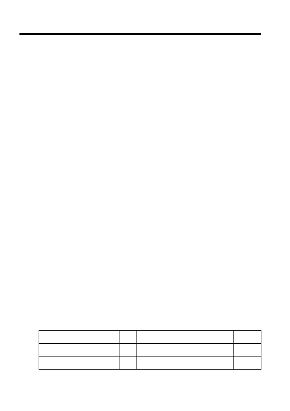
Types and Priority Levels of Parent Drawings
Parent drawings are classified by the first character of the drawing number (A, I, S, H, L)
according to the purpose of the process. The priority levels and execution conditions are as
shown in the following table.
Table 3.3 Types and Priority Levels of Parent Drawings
Type of Parent
Drawing
Role of Drawing
Priority
Level
Execution Condition
Number of
Drawings
DWG.A
Startup process
1
Started when power is turned ON (executed once
only when the power is turned ON)
4
DWG.I
Interrupt process
2
Executed by external interrupts, such as Optional
Module DI interrupts or counter interrupts.
8